Nixie · Volume 9
Enclosure, Finishing & the Themed/Steampunk Treatment
Mounting fragile glass, keeping the 170-volt rail off touchable metal, and dressing the clock in brass — up to a WWII-cryptography design study
Every volume before this one has lived on the bench: a boost board with the probes still hanging off it, a row of tubes in a breadboard jig, a ZM1210 lit up in a clamp to prove the firmware counts. This volume is about the last twenty percent of the project that takes the most time and earns the second glance — turning a working circuit into an object that can sit on a shelf, be handled by people who have no idea there are two hundred volts inside it, and do justice to the warm orange glow that motivated the whole build. The nixie clock invites this kind of finishing more than almost any other electronics project, because the display is already beautiful: a stack of sculpted metal numerals wrapped in cold neon fire, a small miracle of 1950s industrial design that wants to be shown off. The community gravitates, as the scope-clock builders do in the sibling Scope volume on the same subject (Vol 11 of that series), toward two overlapping aesthetics — the restored-instrument look and the brass-and-glass steampunk look — and toward one genuinely original theme collected in this hub: dressing the clock as a piece of WWII cryptographic machinery, the Covert Bombe. But before any of that, the enclosure has a mechanical and an electrical job, and getting the skeleton right comes first because every decorative choice that follows is constrained by it. The enclosure is not an afterthought; it is the part of the build the world actually sees, and it is the part that stands between a casual hand and a rail that, per the hazard tiers of Vol 10, sits well above the threshold where a sustained DC shock becomes hard to let go of.
9.1 Mounting the tubes
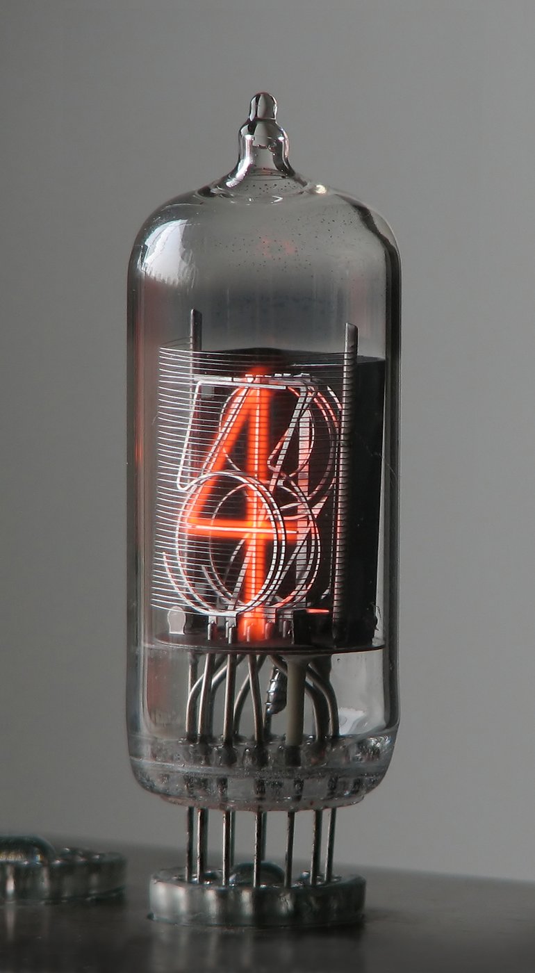
A nixie tube is a small, fragile, fairly expensive glass envelope with a set of thin, often soft wire leads coming out of the base — and on the side-view IN-14 / IN-18 family those leads are long, easily bent, and easily fatigued. The display tubes of Vol 2 cost more than the board they sit on, so how they are held is the first decision of the enclosure, and it splits immediately into two camps: sockets versus direct-solder.
Sockets are the conservative, serviceable choice. A nixie sits in a ring of individual machined-pin (turned-pin) socket receptacles, or in a purpose-made socket, so a tube can be pulled and replaced without touching a soldering iron — which matters because nixies are a consumable: a poisoned or worn cathode (the failure modes of Vol 2) means swapping the tube, not the board. The Russian IN-12 and IN-14 have a well-supported ecosystem of socket pins for exactly this reason. The cost is a little extra height, a little extra unreliability at each mechanical contact, and the need to keep the pin spacing honest. Direct-soldering the tube leads into the PCB is lower-profile, mechanically solid, and electrically the most reliable — but it makes tube replacement a desoldering job, and on the long-lead side-view tubes it puts all the handling stress on the solder joint unless the leads are independently supported. The worked ATMega build of Vol 6, with its end-view ZM1210 tubes, sidesteps some of this because the ZM1210’s leads exit the base in a compact circle that drops straight into a footprint.
The cleanest mechanical answer for either camp is a dedicated tube-holder PCB: a thin board, often separate from the driver board and connected by a ribbon or pin header, whose only job is to present a tidy footprint and locate the tubes at an exact spacing and height. Jeff’s lab makes this trivial — a tube-holder PCB is a two-layer board with no HV stress of its own, well within the reach of a home CNC-routed or commercially-ordered PCB, and a 3D-printed or laser-cut acrylic spacer above it can capture the tube bodies at the right height so the soft leads never carry the glass. For a display-only mount with no PCB at all, an acrylic-and-standoff stand — two laser-cut acrylic plates separated by threaded standoffs, the upper plate drilled to pass the tube leads and cradle the bases — is the iconic “floating numerals” presentation, and it is a five-minute job on the laser cutter once the lead-circle diameter is measured.
Whatever holds them, three handling disciplines protect the glass and the leads. Spacing: lay the tubes out far enough apart that the side-glow of one does not wash into its neighbour and that fingers can get between them to seat each one; the digit height of the chosen tube (Vol 2’s orientation table) sets the minimum pitch. Pin handling: bend nixie leads once, gently, with round-nose pliers gripping between the glass seal and the bend so the seal never takes the strain — a lead flexed repeatedly will work-harden and snap off flush with the glass, which is usually fatal to the tube. Protecting the glass: never let a clamp, a standoff, or a bezel put a point load on the envelope; line any hard contact with silicone, cork, or a printed TPU collar, exactly as the scope builders cradle their CRTs. Nixies do not implode — there is no kilovolt vacuum behind a heavy faceplate — but a cracked envelope lets air in and kills the tube just the same.
9.2 Case materials and fabrication
With the tubes mounted, the case is the form that wraps them — and the single decision that drives that form is the tube’s viewing direction, the side-view-versus-end-view split introduced in Vol 1 and detailed in Vol 2. The two layouts want fundamentally different boxes.
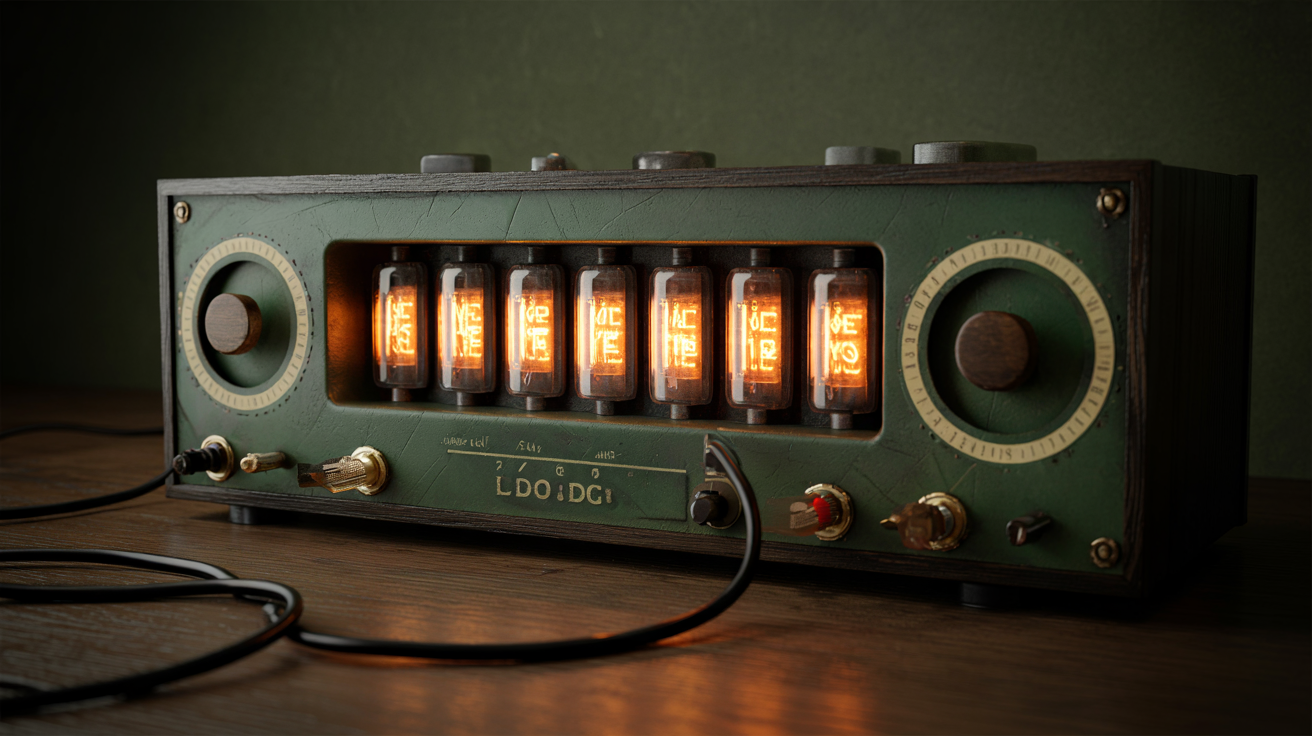
A side-view layout (the iconic IN-14 / IN-18 look, numerals standing upright and read through the side of the glass) wants the tubes above the case, glass exposed, read horizontally from across a room. The enclosure becomes a low plinth or a horizontal bar that hides the boards and presents the tubes on top like a row of little lamps; the front face is the long side of the box. A top-read / end-view layout (the IN-12 or the Vol 6 ZM1210, looking down the axis of the tube at the numeral stack) wants the tubes either laid flat on a board read from above — a tray or slab form, often tilted toward the viewer — or stood vertically and read down a recessed well. The end-view tube hides its own leads better and tolerates a more enclosed case, which is part of why it suits a themed build where the glass peers out through an aperture rather than standing proud. Decide the layout first; it sets the proportions of everything else.
The material choices, in rough order of how forgiving they are on the safety topology of § 9.3:
- Wood. A hardwood carcass or base — oiled, stained, or left raw — is warm, classic, and, crucially, an insulator. A wooden box with the HV board floated on insulating standoffs inside it is one of the most forgiving safety topologies available, because the structure itself can never become live. Jeff’s CNC handles pockets, lead-pass slots, and inlays; the laser engraver burns dial legends and maker’s marks straight into the grain.
- Acrylic and other plastics. Laser-cut acrylic is the fastest route from a sketch to a finished case and the natural home of the “floating numerals” stand of § 9.1 — clear or smoked plates, captive standoffs, edges that glow. It is insulating, dimensionally precise off the laser, and trivially iterated. Smoked or bronze-tint acrylic is also a built-in diffuser/bezel (§ 9.4). The caution is heat: keep acrylic away from any part that runs warm.
- Metal. Sheet brass, aluminium, or steel gives the instrument-grade look and the rigidity for a heavy build — but a conductive case is a safety commitment, not a free choice (§ 9.3). Aluminium folds and CNCs cleanly; brass is the steampunk metal of § 9.4. Every metal case must be grounded or guaranteed unreachable by HV, with no middle ground.
- 3D-printed enclosures. For Jeff’s lab the printers are the default prototyping path and a perfectly good final material: print the plinth, the tube-holder collars, the bezel ring, the internal standoffs and HV-board insulating brackets, the snap-fit back panel. Print insulating brackets in PETG or ABS rather than PLA where any warmth is expected, and use the printer’s freedom to design captive, finger-proof vents (§ 9.3) directly into the wall. A printed master can also be the pattern for a cast or a vacuum-formed shell if a smoother final finish is wanted.
The practical workflow this lab supports is to print the first case, fit and adjust the tube spacing and the board mounts in cheap plastic, then re-make the keeper in wood (CNC + laser) or brass once the geometry is proven. Nothing about the form needs to be guessed.
9.3 HV clearance and insulation inside the enclosure ⚠
The recurring constraint of the whole nixie series, restated as an enclosure rule: the box is a high-voltage enclosure first and a pretty object second. The anode supply of Vol 3 produces roughly 170–200 V DC, and — the fact that makes a nixie supply deceptively dangerous — its filter and reservoir capacitors stay charged after the clock is unplugged. A steampunk shell, by its nature, is often built largely of conductive metal. Those three facts drive everything in this section. The full discipline lives in Vol 10 and the hub-wide safety baseline; what follows is the enclosure-specific subset.
Keep live nodes away from touchable metal. The single rule that prevents the worst accident: every external metal surface a user can touch — a brass skin, a bezel, a bolt head, a metal foot — must be either bonded to protective earth so a fault trips the supply instead of waiting for a hand, or guaranteed by construction that no live node can ever reach it. The dangerous build is the mixed one: a wooden or printed box with a handsome floating brass bezel and brass bolt heads that are bonded to nothing, so that a single chafed anode lead can turn the trim into a charged, isolated electrode waiting for a finger. Bond the metal, or guarantee it unreachable — never neither. And note that patina, lacquer, and the oxide on raw brass are all insulators: a bonding contact must be a bare, star-washered point that the finishing chemistry of § 9.4 never covers.
Creepage and clearance. Two distances govern HV layout. Clearance is the shortest gap through air between two conductors; creepage is the shortest path along the surface of an insulator between them. High voltage arcs across too-small clearances and tracks — carbonizes a permanent conductive path — across too-small creepage, especially on a dusty or humid surface. At 170–200 V the numbers are far gentler than a CRT’s kilovolts, but they are not zero, and the rule from the safety baseline is explicit: do not compromise spacing for a tighter steampunk enclosure. Keep the boost converter’s output, the reservoir capacitor terminals, and the anode bus physically clear of the chassis and of signal wiring; give a wire that must pass near grounded metal slack and route it away rather than along the metal; leave no sharp wire ends or unfiled burrs in the HV zone, because points concentrate field. The enclosure’s job is to provide the room those distances need, which is a reason not to cram a nixie clock into the smallest possible tin.
Insulating the HV board. Float the high-voltage board on nylon or PTFE standoffs, not metal, with generous air gap to any metalwork — and in a printed or metal case, give it a printed insulating tray or a conformal coat over the HV traces so a shifted wire cannot land on the chassis. Strain-relieve the anode lead and the board-to-tube harness so a tug or a vibration lands on a clamp, not a solder joint, and so the anode lead — which carries the highest voltage in the clock — cannot flop against the case. Fit bleeder resistors across the HV rail so the reservoir self-discharges when power is removed, and design the wiring so that opening the back panel does not expose a charged capacitor to a reaching hand. That single habit, more than any finishing choice, separates a clock admired for years from one that bites its maker.
Ventilation. The boost converter and the dropping resistors dissipate some heat, and a sealed decorative box will run warm. Ventilation is a requirement, but it competes with keeping fingers and conductive objects out: the resolution is convection venting — low inlets, high outlets, sized and placed so nothing conductive (a paperclip, a curious finger, a cat’s whisker) can be poked through to reach a live node. Louvers, a perforated brass screen, the gaps between decorative slats, or finger-proof vents printed directly into a 3D wall all work and all read as period-correct on a themed shell.
9.4 Finishing and the steampunk treatment
With the skeleton sound and the HV discipline internalized, the decorative work begins. Two overlapping styles dominate the nixie community and share a material palette and a philosophy — honest materials, visible making, a deliberate patina of age. The restored-instrument look has the clock pretend to be a piece of 1950s lab gear: wrinkle-finish steel, engraved Bakelite or aluminium panels, turned bezels, a row of nixies behind glass like a frequency counter’s readout. The steampunk look is the Victorian-industrial fantasy of what an electric clock should have looked like: brass, copper, wood, leather, exposed mechanism. Both suit nixies extraordinarily well because the tube is itself an anachronism, a glowing artifact that looks like it belongs in either world.
Brass, copper, and patina. Brass and copper are the signature metals — warm, workable, and they take a patina beautifully. Brass sheet (0.5–1 mm) forms by hand or over a brake for skins and bezels; brass and copper pipe, fittings, flanges, and valves become structure and trim; copper sheet ages to greens and browns that read instantly as salvaged. A bright polished clock looks like a trophy; an aged one looks pulled from a forgotten laboratory, which is the steampunk ideal. Patina is earned slowly by leaving bright metal exposed, or induced fast with controlled chemistry — liver-of-sulphur and ammonia-fume methods darken brass and copper, gun blue darkens steel, and selectively polishing the high points after darkening yields the prized rubbed-through highlight-and-shadow. Recall the one electrical caveat throughout: patina and clear-coat are insulators, so any brass part in the earth-bonding scheme of § 9.3 keeps a bare, star-washered contact the chemistry never reaches. Jeff’s laser engraver also opens the door to an etched-brass nameplate — a maker’s plate or dial legend with raised, polished lettering on a gun-blued field — which is the single detail that most finishes an instrument-style clock, whether produced by laser-engrave-and-fill or by the toner-transfer-and-ferric-chloride process the scope-clock builders document at length.
Diffusers, bezels, and lighting. A nixie’s glow is its own primary light, and the finishing job is mostly about framing it without competing with it. A bezel — a turned metal ring, a salvaged brass porthole, a clock or camera-lens ring, a printed collar — trims the aperture the tubes look through and must cushion any glass it touches through a soft gasket, never clamp it. A diffuser — smoked or bronze-tint acrylic, etched glass, a thin frost film — softens the side-glow and hides the unlit cathodes and the internal structure behind the lit numeral, deepening the three-dimensional look. Some builders add secondary lighting — an under-glow, an illuminated jewelled indicator, backlit nameplate lettering — but the discipline is restraint: anything that raises the ambient light near the tubes lowers the apparent richness of the glow. Keep any added light low, warm, and pointed away from the numerals. Two presentation extremes both photograph well: the exposed “naked” build, tubes and wiring on open display, the most honest and dramatic and the most hazardous (every live node within reach — treat it as bench equipment, kept from children and pets, ideally behind a clear barrier); and the enclosed build, working parts sealed but vented inside the case with only the glow and the controls showing, safer and more furniture-like and the natural home for the grounded-metal discipline of § 9.3.
This treatment is the nixie-specific slice of a much larger subject. The general enclosure-design patterns, the full brass-finishing and patina recipes, leatherwork, and the curated visual reference of the whole Victorian-industrial aesthetic live in the hub’s Steampunk subproject, which treats steampunk as an aesthetic axis cross-linking into both the nixie and the scope engineering deep dives rather than duplicating them. A builder dressing a nixie clock should cross-read that subproject for styling depth and treat this volume as the part that ties the styling to the specific electrical realities of a 200-volt cold-cathode display. One point bears stating from both sides, because it is where aesthetics and engineering collide: a steampunk shell over a nixie display inherits the display’s high-voltage safety tier. A beautiful brass box does not make the supply behind it any safer; it makes it prettier, which by inviting handling can make it more dangerous. The enclosure is allowed to be a fantasy; the safety is not.
9.5 The Covert Bombe / Enigma themed build
Beyond brass-as-such sits the one genuinely original theme collected in this hub — the Covert Bombe, introduced in Vol 1 and walked through as a project in Vol 8: a nixie clock dressed not as generic Victoriana but as a specific piece of WWII cryptographic machinery. The idea is to use the nixie’s glowing numerals as the “readout” of a fictional codebreaking instrument, marrying the orange glow to the rotors, drums, and crackle-finished panels of the Bletchley Park machines. This volume treats it as a design study, not a finished build — a worked aesthetic concept the on-hand reference imagery exists to seed, rather than a documented construction.
Three reference image sets on disk feed the concept, and each contributes a distinct visual vocabulary:
- The Bombe (the electromechanical Turing–Welchman codebreaking machine, and the modern Bletchley reconstruction). The reference set is full of rotating drums in their multi-coloured rings, the drum-holder frames, driver boards, drive hubs, and the dense rear wiring looms — and crucially of the front general-arrangement and the crackle/wrinkle-finished panels. For a clock this is the richest mine: a bank of nixies can sit where the indicator drums sit, framed by mock drum-rings, with the real machine’s panel proportions and hardware setting the layout. The deep rear-wiring aesthetic is exactly the kind of honest visible mechanism the steampunk philosophy prizes.
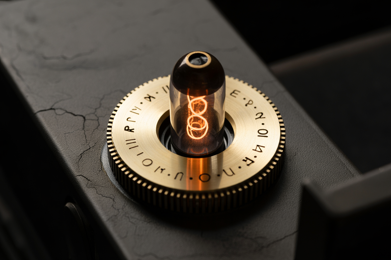
- The Enigma (the cipher machine itself). Its vocabulary is smaller and tighter: the rotors with their alphabet rings and stepping notches, the lampboard, the plugboard with its patch cables, and the hinged wooden case with brass fittings. An Enigma-themed nixie build leans on the wooden-box-with-brass-hardware form (which is also a forgiving safety topology, § 9.3), the alphabet-ring motif around each tube, and a plugboard-style front panel as a control or decorative surface.
- Tatjana van Vark’s machines (a contemporary artisan’s crypto and code-converter instruments). These are the most refined reference — modern, exquisitely machined homages to the period that show how to execute the theme at a jewellery level of finish: turned dials, polished plates, immaculate proportion. They are the quality bar for what the laser, the CNC, and careful hand-finishing in Jeff’s lab could aim at, rather than a literal pattern to copy.
The design moves the concept suggests, drawn from those three sets:
- Rotor / drum motifs around the tubes — printed or machined rings carrying alphabet or numeral collars that echo the Enigma rotor and the Bombe drum, turning each nixie’s bezel into a “wheel.” The CNC turns metal rings; the printers and laser produce the coloured collars and alphabet rings cheaply for fit-up.
- Crackle / wrinkle-finish panels — the signature period texture of military instrument cases, available as a wrinkle-finish spray and ideal for the front and side panels to read instantly as 1940s machinery, with an etched or engraved legend plate for the maker’s-mark fiction.
- Period hardware — slotted screws, brass corner brackets, leather strap handles, a hinged wooden case, panel-mount toggle switches and indicator jewels, so the controls and fasteners match the era rather than fighting it.
- The fiction is the framing, the engineering is unchanged — underneath the drums and the crackle finish sit the same Vol 3 supply, the same Vol 4 drivers, and the same Vol 6 ATMega timekeeping core, inheriting without relaxation the HV clearance and bonding rules of § 9.3 and Vol 10. The crackle panels are decorative skins over a properly insulated or properly grounded chassis; the mock drum-rings cushion the tube glass through gaskets and never clamp it.
Treated as a study, the Covert Bombe is a particularly good demonstration of this volume’s whole thesis: the most evocative nixie enclosures are the ones where a strong narrative drives the form and the high-voltage discipline is honoured underneath it without compromise.
9.6 References (Vol 9)
- The Covert Bombe / Enigma reference image sets,
02-inputs/The Covert Bombe - Enigma/(Pix - Bombe/,Pix - Enigma/,Pix - Tatjana J Van Vark/) — drums, drum-holders, driver boards, rear wiring, crackle panels; Enigma rotors, alphabet rings, plugboard; van Vark’s machined crypto instruments. Source material for the § 9.5 design study. - ATMega Based Cool Nixie Clock — designer files (ZM1210 display schematic, PCB gerbers
nixiepcb.zip, build photos),02-inputs/ATMega Based Cool Nixie Clock/— the worked end-view tube build whose form this volume’s mounting and case sections assume. - Hub Steampunk subproject,
Clocks/Steampunk/CLAUDE.md— the broader Victorian-industrial aesthetic and materials library this volume’s treatment is the nixie-specific subset of. - Sibling Scope/CRT deep dive, Vol 11 (Enclosure, Finishing & the Steampunk Treatment) — the parallel enclosure volume whose structure this one mirrors; the etched-brass-nameplate and cradle-mounting methods are documented there in full.
- Hub-wide safety reference,
Clocks/_shared/safety.md, and Vol 10 (Safety) — the full ~170–200 V HV discipline (discharge procedure, bleeder resistors, creepage and clearance, earth bonding) this volume’s enclosure rules implement. - Vols 2, 3, 4, and 6 of this series — tube families and viewing direction (Vol 2), the boost supply behind the anode rail (Vol 3), the digit drivers (Vol 4), and the worked ATMega ZM1210 build (Vol 6) — the engineering the enclosure wraps.
Comments (0)