Nixie · Volume 8
The Collected Projects
A guided walk-through of every nixie project in this hub — the flagship ATMega build, the Lamina craft clock, the relay-logic novelty, and the Covert Bombe concept
This hub did not start as a deep dive — it started as a folder of things worth keeping.
Four nixie projects were collected into this subproject’s 02-inputs/ before a single
volume was written, and each one was kept for a different reason: one because it is a
complete, owned, buildable design; one because it is a beautiful piece of woodworking
that happens to wrap a nixie kit; one because it counts the time with relays and no
microcontroller at all; and one because it is an idea — a nixie display dressed as a
WWII codebreaking machine — backed by a thick stack of reference photographs and nothing
yet built. The engineering volumes of this series (the high-voltage supply in Vol 3, the
digit drivers in Vol 4, the timebase and counting logic in Vol 5, the full worked build
in Vol 6) draw their examples from these four projects. This volume does the opposite: it
walks each project as a project, says plainly what is on disk, what is notable about it,
and how you would go about reproducing it or drawing on it. Think of it as the guided
tour of the filing cabinet — the overview in Vol 1 §1.6 named these four in a sentence
apiece; here each gets the room it deserves.
A word on what “collected” means, because it sets expectations for the rest of the volume. Two of these projects (the ATMega clock and the relay clock) come with real engineering documents — schematics, datasheets, gerbers, firmware, a bill of materials — and could be put on the bench tomorrow. One (the Lamina clock) is a build narrative, an Instructables how-to whose value is the craft and the enclosure rather than a reusable board file. And one (the Covert Bombe) is a mood board: a large set of reference images and a single inspiring web page, with no schematic because the clock has not been designed yet. The volume treats each at the level it actually exists, and the closing map (§8.5) tags every project with its status so nothing is oversold.
8.1 ATMega Based Cool Nixie Clock — the flagship
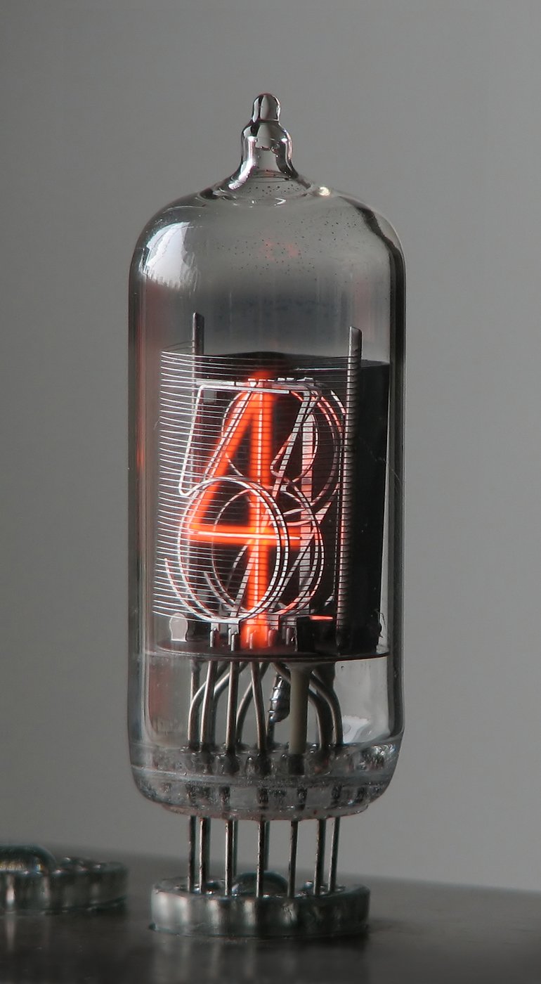
This is the project the engineering volumes are built around, and it is the only one in the collection that is a complete, owned design ready to fabricate. It is an AVR/ATMega clock driving Telefunken ZM1210 end-view tubes (the 15.5 mm digit-height tube introduced in Vol 1 §1.5) through 74141 BCD-to-decimal high-voltage drivers, with the driver inputs fed from a chain of 74HC595 serial-in/parallel-out shift registers so the microcontroller can address every digit over a handful of pins. The high-voltage anode rail and the timekeeping core are exactly the four-subsystem anatomy of Vol 1 §1.1, realised in a board you can hold. The full schematic-to-calibration walk-through is Vol 6; this section is the inventory of what is on disk and why it matters.
8.1.1 What is on disk
The 02-inputs/ATMega Based Cool Nixie Clock/ folder is the richest in the collection.
Grouped by what each file does:
- Schematics.
zm1210-display-atm-7.sch(an EAGLE schematic, with a.sch.bz2compressed copy) is the primary display board — the ZM1210 tubes, their 74141 drivers, and the 74HC595 chain.2D3 Nixie clock Schematic (Multiplexed).pdfis a second, multiplexed variant of the same idea, andnixcct.pdfandseconds.pdfare supporting circuit sheets. The multiplexed variant matters: it is the textbook trade-off of Vol 4 — instead of a permanent driver per tube, the digits are lit one (or one group) at a time in fast rotation, trading a little brightness and some firmware complexity for far fewer high-voltage driver parts. - Driver and MCU references.
74HC_HCT595.pdfis the shift-register datasheet (the part that turns a serial bitstream into parallel driver-select lines), andATMegaManual.pdfis the AVR reference for the microcontroller doing the timekeeping.AtmelInSystemProgramming.pdfis the ISP guide you will need to flash the firmware in-circuit (Vol 6 §“flashing”). - Fabrication and firmware.
nixiepcb.zipholds the PCB gerbers — the actual fabrication output you would send to a board house.nix-in-17_1_1.zipis thenix-in-17firmware with its matchingnix-in-17_schematic_1_1.pdf; the name signals a sibling design sized for the small IN-17 sub-miniature tube (Vol 1 §1.5), a useful cross-check on the firmware’s digit-handling even though this build runs ZM1210s. - Provenance.
OrderHistory.pdfis the parts-order record — effectively a ready-made BOM-with-sources, handy when Vol 6 rebuilds the bill of materials. - Build photos.
img_4090.jpg,img_4091.jpg, andimg_4101.jpgare photographs of the assembled hardware collected as reference — they show the original designer’s build (the LCD reads “By Nina, 2012”), not a first-party build, so they are useful for orientation but are not license-clear to publish.
8.1.2 How to approach reproducing it
Because this design is complete, the path is the cleanest in the series (it is Path 4 in
the Vol 1 decision tree). Open the EAGLE schematic and the gerbers together, confirm the
parts in OrderHistory.pdf against current availability (the ZM1210 and 74141 are both
new-old-stock, so check sourcing first), fabricate nixiepcb.zip, build the
high-voltage supply to the Vol 3 targets, populate the 74141/74HC595 driver chain per
Vol 4, and flash nix-in-17 over ISP. The multiplexed 2D3 schematic is the variant to
study if you want to cut the driver count; the straight zm1210-display-atm-7 schematic
is the one to build if you want every digit independently driven and the simplest
firmware. Vol 6 carries all of this end to end, with the build photos above as the
reference. ⚠ The anode rail on this board sits at ~170–200 V DC behind a filter
capacitor — read Vol 10 before first power-up.
8.2 Awesome / Lamina Nixie Clock — the craft reference
The second project is a different animal entirely. Awesome Nixie Clock/ contains a
single file — Lamina-Nixie-Clock.pdf, a 20-page capture of the Lamina Nixie Clock
Instructable published by zorwick in April 2012. It is not a board design and it is
not a kit; it is a build narrative, and its value to this hub is precisely the part
the ATMega project leaves out: the enclosure and the craft.
8.2.1 What it is
The Lamina clock is a piece of cabinetwork that happens to tell the time in nixie orange. The maker started not from a circuit but from an aesthetic — inspired, he says, by Hellboy’s “Lantern Clock” Instructable — and designed a layered (“lamina”) body in walnut and maple with hand-made brass disks, rods, and gears, the tubes standing in acrylic tubes like specimens in jars. Crucially, the electronics are bought, not designed: the materials list calls for a generic “nixie clock kit” and a 12 V power adaptor, and the document’s energy goes into the woodwork, the brass turning, the finishing, and the assembly. The PDF’s table of contents is a craft sequence — The woodwork → The tanks → The electronics → The rest → Assembling → The final clock — not an engineering one.
8.2.2 What it contributes, and where it cross-references
Lamina earns its place as a two-way reference. As a kit build it is the worked example behind Vol 7’s buy-a-kit path: it shows what “buy the kit, build the body” looks like in practice, and why for many makers the enclosure is the real project once the electronics are a solved, purchased module. As an enclosure it is a direct feed into Vol 9 — the walnut/maple lamination, the acrylic tube “tanks,” and the hand-turned brass are exactly the materials-and-finishing vocabulary that volume develops, and they sit on the warm, machined-brass end of the spectrum that the steampunk treatment pushes further. Read it for the craft, not the schematic; pair it with Vol 7 for the kit selection it deliberately leaves generic, and with Vol 9 for the case it lavishes its attention on.
8.3 The Relay Nixie Clock — counting time with relays
If the collection has a single celebrated build, this is it: a four-digit, 12-hour nixie clock that keeps and displays the time using electromechanical relays — no microcontroller anywhere in the counting and display path. It is the novelty that makes this hub worth assembling, the Path 5 of the Vol 1 decision tree, and the project the relay-logic discussion of Vol 5 is built on. The work is by jbstanley / Catahoula Technologies, documented on the Relay Logic Projects page at electronixandmore.com, and the hub holds both the project writeup and the board’s own datasheet and schematic.
8.3.1 What is on disk
The Relay Nixie Clock/ folder is small but complete enough to understand the machine:
Relay Logic Projects.pdf— the 16-page project narrative. It opens with a primer on doing logic with relays: defining a logic ‘0’ and ‘1’ as either CMOS-style (0 = GND, 1 = Vdd) or by a “floating zero” convention (0 = no connection, 1 = Vdd), then building combinational gates, adders, multiplexers, and flip-flops from DPDT relays in the spirit of the CD4000-series CMOS parts. The author designed a family of 4-bit relay-logic modules (named after their CMOS analogues — anRL4067decoder, anRL4108incrementer, anRL4175D-flip-flop, anRL4079gate array, anRL4519mux) and wired the clock from them before collapsing the design onto one board.RL1200_ds.pdf— the single-board “RL1200” datasheet: a bill of materials and a port map. This is the document that pins down the machine.RL1200_sch.pdf— the full schematic of that single board.Relay Nixie Clock.url/Relays.url— links to the project page (electronixandmore.com/projects/relaylogic) and to the relay part itself (an Omron G2R-2 12 VDC).
There are no first-party photographs of the relay clock in the folder — the imagery lives on the source page — so this section carries no figure of its own.
8.3.2 How it counts and carries
The RL1200 board uses 55 Omron G2R-2 12 VDC DPDT relays (a later revision trimmed this to 54, having found one relay in the minutes decoder unnecessary). The only solid-state parts in the counting story are the timebase: a 4.194 MHz crystal divided down by a CD4521 (with a couple of CD4017 decade dividers) to produce one clock pulse per minute — and even that can be bypassed, the board accepting an external active- low 1 Hz reference “in lieu of the timebase ICs.” Everything downstream of that pulse — the minute and hour counting, the carries, the 12-hour rollover, and the nixie cathode decode — is relays. That is the honest sense in which this is a “no microcontroller” clock: there is no CPU and no firmware; there is a crystal ticking once a minute into a lattice of relay flip-flops and gates.
The counting logic is a small lesson in digital design rebuilt in copper and iron. Each
digit is a relay decade counter built from D-type flip-flop modules; an
incrementer (RL4108-style) adds one on each clock edge, gated by an enable so it
can be held; a decoder (RL4067-style) lights the matching nixie cathode, its common
pin tied to ground for the tube. The 12-hour behaviour is pure combinational relay logic:
“=5”, “=9”, “=11” detectors fire when the hour counter hits those binary values, and
a “>8” detector lights the leading “1” on the tens-of-hours tube for 10, 11, and 12 —
all assembled from relay AND/OR gates (the RL4079 module) and a relay multiplexer
(RL4519) that selects between “increment” and “clear” to roll the counter over. The
high-voltage nixie supply is the one place the board reaches for a switching
controller — an MC34063AP boost regulator generating the anode rail — which keeps the
relay count off the high-voltage line and the relays themselves switching only the
low-voltage logic and the cathode pulls. The mechanism is dissected in Vol 5; here the
point is simply that it works, audibly, with a chorus of clicks once a minute.
8.3.3 Why it is a celebrated build, and how to approach it
The relay clock is beloved for the same reason the nixie tube is: it makes the invisible
visible. A microcontroller clock hides its counting inside a chip; the relay clock
spreads the whole computer out on a board where you can watch (and hear) the carry
propagate. Reproducing it is a very high effort undertaking — 54-plus relays to source,
populate, and debug, and a schematic (RL1200_sch.pdf) to follow exactly — but it is also
the most legible digital machine in the entire hub, and the most rewarding to bring to
life. Catahoula Technologies sells the board and the relay-logic modules for those who
want to build rather than re-engineer it. Approach it as Vol 5’s worked example: read the
relay-logic primer first, build and verify one decade counter module, then scale to the
full four-digit machine. The G2R-2 coils are 12 V, so the dangerous high voltage is
confined to the small MC34063AP supply and the anode resistors — ⚠ still ~170 V, still
read Vol 10.
8.4 The Covert Bombe / Enigma — the themed concept
The fourth project is the outlier, and it is important to say at the top what it is and is not: it is not a built clock, and there is no schematic on disk. It is a concept — an aesthetic direction — for dressing a nixie display as a piece of WWII cryptographic machinery, seeded by the “Covert Bombe” project at bad-dog-designs.co.uk and backed by a large folder of reference photography. It feeds the enclosure and themed-build work of Vol 9, not the engineering volumes. Treated honestly, it is inspiration with homework attached, not a project you can fabricate today.
8.4.1 The idea
The conceit is to take the warm orange glow of a nixie clock and hide it inside the look of the machines that broke the Enigma cipher — the Turing/Welchman Bombe with its ranks of rotating drums, or the Enigma itself with its lettered rotor windows and plugboard. Where the Lamina clock (§8.2) reaches for warm wood and brass, the Covert Bombe reaches for olive-drab steel, lettered drums, and the deliberately covert trick of a modern display masquerading as 1940s electromechanical hardware. It is the most narrative of the four projects: the clock is a prop in a story about codebreaking.
8.4.2 The reference material on hand
The Covert Bombe - Enigma/ is organised as three image sets, and the breadth is the
point — this is a designer’s mood board:
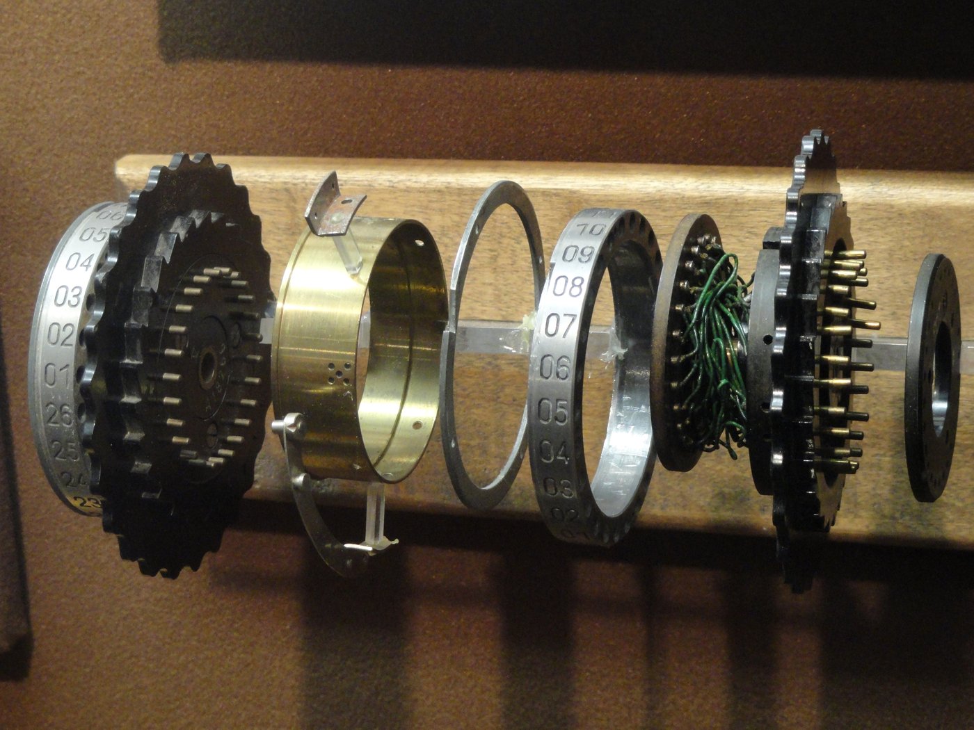
Pix - Bombe/— the Covert Bombe build itself and Bombe machinery: front general- arrangement shots, the rotating drums and their holder, the drive hub and spindle, driver boards, rear wiring, an “exploded” view, and in-progress assembly photographs. These are the closest thing in the folder to a build reference, and they show how a covert nixie display can be choreographed behind drum-and-spindle hardware.Pix - Enigma/— a wide survey of Enigma and related cipher machines: four-rotor and eight-rotor Enigmas, rotor-and-spindle close-ups showing contacts, ratchet and notch, the plugboard, the lettered rotor windows, museum exhibits, and adjacent rotor machines (a Hebern rotor pair, a Japanese secure teletype). This is the visual vocabulary of “what cryptographic machinery looks like.”Pix - Tatjana J Van Vark/— the standout reference: photographs of Tatjana van Vark’s hand-built modern cryptographic machines (her code converter and crypto-machine series). Van Vark is a Dutch maker whose mechanical instruments are exquisitely engineered art objects, and her work is the aspirational ceiling for what a themed nixie build can aim at — the bridge between “looks old” and “is beautifully made.”
8.4.3 How it feeds the theme work
The Covert Bombe’s role is to seed Vol 9’s themed/steampunk treatment. There is no counting logic to reproduce — pick any of the buildable clocks in this collection (the ATMega flagship of §8.1, or the relay clock of §8.3 if you want the electromechanical honesty to match the theme) and let the Bombe imagery drive the enclosure: the lettered drums, the drive-hub aesthetic, the deliberate concealment of a modern display inside period-looking hardware. The Tatjana van Vark set is the reminder to aim high on the making. Carry it forward as inspiration, credited to its source page, and treat it as Vol 9’s material rather than anything you can fabricate from these files alone.
8.5 How the projects map to the series
The four projects are not redundant — each occupies a different point in the space of “how you get a nixie clock” (Vol 1 §1.3) and each is documented by a different set of volumes. The map below tags every project with the volumes that cover it and its honest status, so it is clear at a glance which are buildable today and which are reference or inspiration.
Table 1 — 8.5 How the projects map to the series
| Project | What it is | Covered in | Status |
|---|---|---|---|
| ATMega Based Cool Nixie Clock | AVR/ATMega clock, ZM1210 tubes via 74141 + 74HC595; straight and multiplexed variants; full schematic, gerbers, firmware, build photos | Vols 3–6 (engineering + full build); this §8.1 | Owned design — buildable now |
| Awesome / Lamina Nixie Clock | Instructables craft build (walnut/maple/brass) around a bought nixie kit | Vol 7 (kit path), Vol 9 (enclosure); this §8.2 | Reference — narrative, not a board |
| Relay Nixie Clock (RL1200) | 4-digit 12-hour clock counting with 54–55 DPDT relays; crystal timebase only; MC34063AP HV supply | Vol 5 (relay logic), this §8.3 | Novelty — buildable, very high effort |
| The Covert Bombe / Enigma | Aesthetic concept: nixie display dressed as WWII codebreaking hardware; large reference image set incl. Tatjana van Vark | Vol 9 (themed/steampunk); this §8.4 | Concept — inspiration, not yet built |
Read across the table and the shape of the hub appears: one project to build (§8.1), one to learn craft from (§8.2), one to build for the sheer audacity of it (§8.3), and one to dream toward (§8.4). The engineering volumes give you the subsystems; these four projects give you the reasons.
8.6 References (Vol 8)
- ATMega Based Cool Nixie Clock — designer files:
zm1210-display-atm-7.sch(+.sch.bz2),2D3 Nixie clock Schematic (Multiplexed).pdf,nixcct.pdf,seconds.pdf,74HC_HCT595.pdf,ATMegaManual.pdf,AtmelInSystemProgramming.pdf,nixiepcb.zip(PCB gerbers),nix-in-17_1_1.zip+nix-in-17_schematic_1_1.pdf(firmware),OrderHistory.pdf, build photosimg_4090.jpg/img_4091.jpg/img_4101.jpg. Held in02-inputs/ATMega Based Cool Nixie Clock/. - Awesome / Lamina Nixie Clock — Lamina Nixie Clock Instructable by zorwick (2012),
Lamina-Nixie-Clock.pdf. Held in02-inputs/Awesome Nixie Clock/. - Relay Nixie Clock — Relay Logic Projects by jbstanley / Catahoula Technologies
(electronixandmore.com/projects/relaylogic):
Relay Logic Projects.pdf,RL1200_ds.pdf(board datasheet / BOM),RL1200_sch.pdf(schematic),Relay Nixie Clock.url,Relays.url(Omron G2R-2 12 VDC relay). Held in02-inputs/Relay Nixie Clock/. - The Covert Bombe / Enigma — concept page at bad-dog-designs.co.uk/blog/the-covert-bombe;
reference image sets
Pix - Bombe/,Pix - Enigma/,Pix - Tatjana J Van Vark/. Held in02-inputs/The Covert Bombe - Enigma/. - Cross-referenced volumes: Vol 1 (overview & §1.6 project list), Vol 3 (HV supply),
Vol 4 (digit drivers, multiplexing), Vol 5 (timebase & relay logic), Vol 6 (the full
ATMega build), Vol 7 (kits & finished clocks), Vol 9 (enclosure & themed treatment),
Vol 10 (safety). Hub-wide
_shared/safety.mdfor the HV discipline.
Comments (0)