Nixie · Volume 2
How a Nixie Tube Works
The cold-cathode glow discharge that sculpts a glowing numeral, and the strike/maintain physics that governs how you drive it
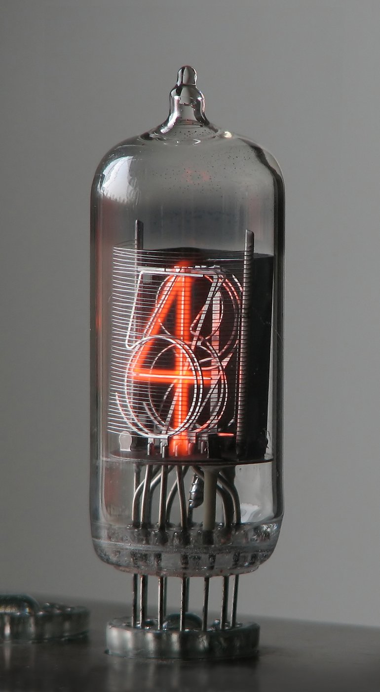
A nixie tube is the rare piece of twentieth-century electronics whose operating principle you can read straight off its face: the glowing “7” is a wire bent into the shape of a 7, and the orange light wrapped around it is a thin shell of ionized neon clinging to that wire because the wire has been pulled a couple of hundred volts below the surrounding anode. There is no phosphor, no filament, no junction — just a low- pressure gas, a sculpted cathode, and a mesh anode, with a strong electric field doing all the work. That makes the nixie one of the few displays where understanding the physics is the same thing as understanding the part: once you know how a cold-cathode glow discharge ignites, where it sits, why it has two characteristic voltages instead of one, and why it slowly poisons itself if you neglect it, you know everything the rest of this series needs you to know to power one (Vol 3), drive its digits (Vol 4), and keep it alive for decades (this volume’s § 2.5–2.6). This volume is the physics reference the engineering volumes lean on; it carries forward the one-sentence fact from Vol 1 — that the discharge has a higher voltage to strike and a lower one to maintain, and that the whole art of driving nixies lives in that gap — and unpacks it completely.
2.1 The cold-cathode glow discharge
Everything a nixie does is one physical phenomenon: a glow discharge in a low- pressure gas. Seal a little neon at a fraction of an atmosphere between two electrodes, raise the voltage between them, and at first essentially nothing flows — the gas is an insulator, and only a vanishing leakage current passes as stray cosmic-ray and background ionization liberate the occasional electron. This is the Townsend (dark) discharge regime: the field accelerates those few free electrons, but not yet hard enough to sustain anything. Keep raising the voltage and each accelerated electron eventually gains enough energy between collisions to knock a second electron off a gas atom, that pair makes four, and the multiplication runs away in a Townsend avalanche. At the breakdown (strike) voltage the gas transitions abruptly from insulator to conductor, a self-sustaining discharge lights, and the voltage across the tube drops even as the current climbs — the hallmark negative-resistance behavior that § 2.3 builds the whole drive scheme around.
2.1.1 Why the glow is orange-red
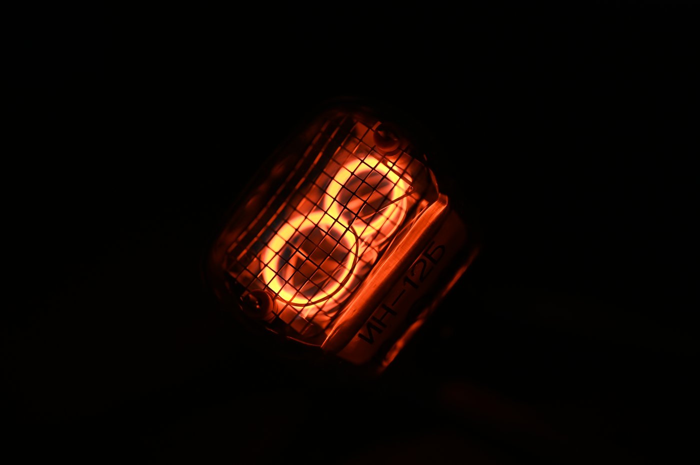
The light is neon being neon. When an energetic electron collides with a neon atom it kicks one of the atom’s electrons up to a higher energy level; a few nanoseconds later that electron falls back, and the energy comes out as a photon at one of neon’s characteristic wavelengths. Neon’s strongest visible emission lines cluster in the orange-to-red band, roughly 585–640 nm, with a tail of weaker lines running up toward 700 nm, and the eye integrates the lot into the unmistakable warm orange that every neon sign and every nixie tube shares. There is no filter and no phosphor choosing that color — it is simply where neon’s electronic transitions land. Fills based on other gases glow other colors (argon-and-mercury runs blue-violet, which is why some “blue” indicator tubes exist), but the classic nixie is neon, and neon is orange-red. The exact hue shifts slightly with the trace additives discussed below, but the family resemblance to a neon lamp is no coincidence: a nixie is a neon lamp with ten differently-shaped cathodes.
2.1.2 The negative glow — why the numeral, and only the numeral, lights
A DC glow discharge is not uniform along its length. Between cathode and anode it organizes itself into a stack of regions — the thin cathode dark space right at the cathode surface, then the bright negative glow, then the Faraday dark space, then the positive column that fills most of the gap in a long tube like a neon sign. The region that matters for a nixie is the negative glow, because it is by far the brightest and it forms immediately adjacent to the cathode surface, hugging its contour within a fraction of a millimeter. A nixie is built so the negative glow is essentially all you see: the cathode is a numeral-shaped wire, the negative glow sheaths that wire in a conformal orange skin a millimeter or so thick, and the result is a glowing figure that appears to float. Because the glow attaches to whichever cathode is pulled negative, lighting a different digit is simply a matter of switching which numeral-shaped wire is connected to the discharge — the gas and the anode never move. This is also why a nixie’s digit has visible depth and a soft halo rather than a hard edge: the glow is a three-dimensional shell of ionized gas around a wire, not a lit surface.
2.1.3 The gas fill — neon, Penning mixtures, and a trace of mercury
The fill is neon at low pressure — typically a few tens of torr — but rarely pure neon. Most nixie fills are a Penning mixture: neon with a small percentage of argon (or another gas) added deliberately to lower the strike voltage. The trick exploits the Penning effect — argon’s ionization energy sits below the energy of neon’s long-lived metastable excited states, so an excited neon atom that bumps into an argon atom can ionize it. That extra ionization pathway means the avalanche reaches self-sustaining levels at a lower applied voltage than pure neon would need, which is why a real nixie strikes around 170 V rather than the considerably higher figure pure neon at the same pressure would demand. Many tubes also carry a trace of mercury vapor in the fill. The mercury does little for the light, but it dramatically slows the cathode sputtering that otherwise ages the tube (§ 2.5), giving a mercury-bearing nixie a self-healing quality the pure-neon types lack. The penalty is that mercury can migrate and condense over decades of storage, which is one of the NOS-tube realities of § 2.6.

2.2 Anatomy of a nixie tube
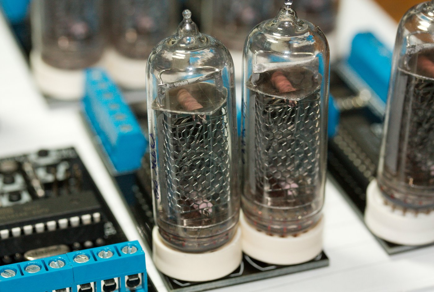
Open the glass and a nixie is mechanically simple — three functional pieces and the envelope that holds them in vacuum-tube vacuum (or rather, low-pressure gas). The anode is a sparse grid or mesh of fine wire, placed across the front of the tube where it will not block the view; it is held at the positive supply potential and is deliberately open so you look through it at the cathodes behind. The cathodes are the stars: a stack of ten wire electrodes, each bent into the outline of one numeral 0–9, insulated from one another and layered front-to-back at slightly different depths so they nest without touching. Lighting a digit means connecting that one cathode to the discharge through the drive electronics (Vol 4) while the other nine float; the negative glow forms only on the energized one. Many tubes add an eleventh cathode for a decimal point (or two, left and right), used as a colon or separator in clocks. A getter — a small deposit of reactive metal flashed onto the glass during manufacture, visible as the silvery patch inside many tubes — continuously absorbs stray gas molecules that would otherwise contaminate the fill, and a glass envelope on a base with pins (or flying leads on wire-ended types) brings each cathode and the anode out to the socket.
The hero image of this volume — and Figure 1.2 of Vol 1 — is a Telefunken ZM1210 with its coating removed, and it shows the anatomy directly: the wire anode mesh stands in front, the stacked numeral cathodes nest behind it, and the lit digit is simply the one cathode currently pulled to ground. The ZM1210 is an end-view tube (you read it down the axis) with eleven cathodes — ten digits 0–9 plus one decimal point — and a 15.5 mm digit height; it is the exact tube the hub’s worked ATMega build drives (Vol 6), so it recurs throughout the series.
The depth-stacking of the cathodes is the source of the nixie’s most-loved visual quirk and its one ergonomic flaw. The look: because the numerals sit at different distances from the viewer, a nixie has genuine three-dimensional presence — the figures appear suspended at varying depths rather than printed on a plane. The flaw: the rearmost digits are partly seen through the wires of the ones in front, so in some tubes a “0” or “9” placed deep in the stack is faintly shadowed by the digits ahead of it. Tube designers chose the stacking order to put the most-used digits where they read cleanest, and end-view tubes like the ZM1210 sidestep the problem somewhat by presenting the stack face-on rather than edge-on.

2.3 Strike voltage, maintaining voltage, and the mandatory anode resistor
The single most important electrical fact about a nixie is that it has two characteristic voltages, not one, and they differ by enough to matter. The strike (ignition) voltage is the anode-to-cathode voltage at which the gas breaks down and the digit first lights; for common clock tubes it sits around 170 V, varying from roughly 140 V to 200 V across tube types and slightly with temperature, age, and ambient light (a little background illumination or radiation seeds the first electrons and lowers the strike voltage marginally). Once the discharge is lit, it does not need that much voltage to keep going. The maintaining (sustaining) voltage — the voltage the tube actually drops while it conducts — is markedly lower, typically 120 V to 150 V. The tube ignites at the high number and then settles to the low one.
This is the negative-resistance behavior of § 2.1 made concrete, and it has a hard engineering consequence. Once struck, the tube’s voltage drops and stays roughly constant regardless of how much current flows through it — the device looks, over its operating range, almost like a constant-voltage drop rather than a resistor. Connect a nixie straight across a voltage source above its strike point with nothing to limit the current and the physics runs away: the tube fixes its voltage at ~140 V, the source tries to push unlimited current to make up the difference, the current climbs until the discharge overheats the cathode, the cathode sputters violently, and the tube destroys itself in short order. A series current-limiting resistor on the anode is therefore mandatory, not optional. It is the load line that turns an unstable negative-resistance device into a stable, predictable display: the resistor drops the difference between the supply and the tube’s maintaining voltage, and that drop sets the digit current.
2.3.1 Sizing the anode resistor
The relation is Ohm’s law across the resistor. The supply sits at V_supply, the tube holds itself at V_maintain, so the resistor carries the difference, and the current through it (which is the digit current) is fixed by the resistor value:
R = (V_supply − V_maintain) / I_digit
Worked example, for a typical clock tube run at 2 mA from a 180 V rail with a 140 V maintaining drop:
R = (180 V − 140 V) / 2 mA = 40 V / 0.002 A = 20 kΩ
So a 20 kΩ anode resistor sets a 2 mA digit. The power it dissipates is small — P = I²R = (0.002 A)² × 20 kΩ = 0.08 W, comfortably inside a ¼ W part — but it is doing essential safety work, not trivial work. A few design notes fall out of the formula. First, the calculation depends on V_maintain, which varies tube-to-tube and drifts with age, so the actual current varies somewhat even with a fixed resistor; the resistor is a soft current source, not a precise one, and that is fine for a display. Second, the larger the headroom (V_supply − V_maintain), the less sensitive the current is to tube-to-tube V_maintain spread — running the rail well above strike (say 180–200 V) gives a more uniform set of digits than running it just barely above. Third, in a multiplexed clock that shares one anode resistor across several time-shared tubes, or that puts the resistor on the anode of each tube, the sizing is the same but the duty-cycle correction of § 2.4 applies. The supply that produces this ~170–200 V rail is Vol 3’s entire subject; the drivers that connect the chosen cathode to ground beneath it are Vol 4’s.
2.4 Current and brightness
Within the glow region, brightness tracks current: more electrons mean more excitation collisions mean more photons. The useful operating window for a clock-sized digit is roughly 1.5 mA to 3 mA per lit cathode, with ~2.5 mA a common nominal for the popular Soviet side-view tubes. Below about 1 mA the negative glow may not fully cover the cathode — the digit looks patchy, with parts of the numeral dim or unlit, because there is not enough discharge to wrap the whole wire. Above the rated current the digit is brighter but you are buying that brightness with accelerated sputtering and a shorter life (§ 2.5–2.6), and beyond the tube’s maximum you risk damage. The datasheet figure is a balance of legibility against longevity, and for an always-on clock it pays to sit at the lower-to-middle end of the range rather than driving the tubes hard.
Brightness is set by the same two numbers as the current, through the resistor relation of § 2.3: raise V_supply or lower R and the digit current rises, brightening the display; do the opposite and it dims. That gives the clock designer two clean dimming levers. DC dimming changes the steady current — a larger anode resistor (or a lower rail) for a dimmer night mode. PWM dimming keeps the current at its nominal value but switches the digit on and off rapidly at a duty cycle below 100%, so the average brightness drops while each “on” instant still runs the tube at a healthy current; this is generally kinder to the tube than running it continuously at very low current, because it keeps the glow fully formed during the on-time. PWM is also how a multiplexed display shares drivers across digits without each tube looking dim — the duty cycle and the perceived brightness are the knobs, and the peak current during the on-time is set to keep the average where you want it. The mechanics of multiplexing and the choice between DC and PWM dimming are Vol 4’s territory; the physics here is just that brightness follows current, current follows the resistor and rail, and there is a floor below which the glow stops covering the numeral.
2.5 Cathode poisoning and the anti-poisoning routine
The slow enemy of every nixie is cathode poisoning, and it is a direct consequence of how the glow works. The energetic positive ions that bombard the cathode during the discharge do not just excite the gas — they physically knock metal atoms loose from the cathode surface, a process called sputtering. Those liberated atoms drift off and redeposit elsewhere inside the tube: on the glass, and crucially on the other, unlit cathodes. Over time a cathode that is rarely lit accumulates a film of sputtered material and adsorbed contaminants that raises its local work function and makes it harder to strike and harder to light evenly. The visible symptoms are characteristic: a hazy or cloudy film on the glass in front of the digit stack, and blue or pink spots and patches on a digit that should glow uniform orange, sometimes with parts of the numeral refusing to light at all. The effect is worst on the digits a clock seldom shows — in a 24-hour HH:MM:SS display the tens-of-hours tube may only ever need to show 0, 1, and 2, so its 3-through-9 cathodes sit cold for years and poison while the well-exercised digits stay clean.
The cure is to exercise every cathode periodically, and the standard firmware trick is the cathode-cycling or “slot-machine” routine: at intervals (commonly once an hour, or for a stretch at a set time each day) the clock rapidly cycles all ten digits on every tube — the display spins like a slot machine — so that each cathode, including the rarely-used ones, carries the discharge for a while. Lighting a poisoned cathode actually reverses the deposition: running the glow on it sputters the contaminant film back off, cleaning the surface. A minute or two of cycling per day is generally enough to keep a set of tubes healthy indefinitely, which is why the routine is near-universal in modern nixie-clock firmware and is one of the items the worked build’s firmware handles (Vol 5). Tubes with a mercury-bearing fill (§ 2.1.3) are partly self-healing — the mercury suppresses the sputtering in the first place, so they poison more slowly and recover more readily — but even a mercury tube benefits from a cathode-cycling routine, and the pure-neon types depend on it.
2.6 Lifetime and failure modes
A nixie is, by the standards of glowing display technology, extraordinarily long-lived — it runs cool, has no filament to burn out, and no phosphor to deplete. Manufacturer lifetime ratings are commonly quoted in the tens of thousands of hours (figures of order 50,000 hours and up appear in datasheets), and a tube that is run within its current rating and exercised against poisoning (§ 2.5) can realistically last a decade or more of continuous clock service. But “tens of thousands of hours” is a rating, not a guarantee, and several distinct mechanisms eventually end a tube’s life:
- Cathode poisoning run to failure — if poisoning is never reversed, the affected cathodes eventually will not light at all (§ 2.5). This is the most common avoidable failure and the reason the anti-poison routine exists.
- Getter exhaustion — the getter has a finite capacity to absorb stray gas. Once it is saturated (visible as the silvery flash turning white/cloudy), contaminants accumulate in the fill and the discharge degrades.
- Gas contamination and fill change — outgassing from internal parts and slow permeation shift the gas composition over decades; the strike voltage creeps up and the glow color and uniformity drift.
- Mercury migration — in mercury-bearing tubes the mercury can migrate and condense in cool spots over long storage, leaving droplets on the glass and depleting the vapor that protected the cathodes.
- Mechanical and seal failure — a cracked glass-to-metal seal, a fractured envelope, or a broken internal weld lets air in and kills the tube outright; this is also the risk that makes physically handling NOS tubes a matter of care.
Those last points define the new-old-stock (NOS) reality that dominates nixie sourcing today (Vol 7). Most tubes a builder buys were manufactured in the 1960s–1980s and have sat in storage for decades. A well-stored NOS tube is often indistinguishable from new and will give a full life; a poorly-stored one may strike high, glow unevenly, show mercury droplets, or have a soft vacuum from a slow leak. The practical consequences — testing a tube before committing it to a build, burning in a NOS tube at rated current to clean it up, matching tubes for brightness across a display, and budgeting for spares because the supply is finite and non-renewable (save for Dalibor Farný’s modern hand-made tubes) — are all Vol 7’s subject. The physics to carry forward is simply that a nixie ages gracefully and slowly along several axes at once, and that most of those axes are kept in check by running it gently and exercising every cathode.
2.7 Tube families and sizes
There is no one nixie; there are dozens of types from a handful of manufacturers, and the practical differences for a clock builder come down to viewing direction, digit height, and origin (which drives availability and price today). Vol 1 § 1.5 gave the first orientation — side-view versus end-view, and the headline tubes — and the table below fills it out across the families this series refers to. As Vol 1 covered, the Soviet IN-series dominates the surplus market because it was produced in enormous quantity, which is why the cheapest plentiful tubes today are Russian; the Western Telefunken/Philips ZM-series and Burroughs types are the classics of the original era and the ZM1210 is the hub’s worked-build tube.
Table 1 — 2.7 Tube families and sizes
| Type | Origin | View | Digit height | Notable use / character |
|---|---|---|---|---|
| IN-12 (ИН-12) | Soviet | end-view | ~18 mm | Flat PCB-mount end-view tube; very common and cheap; popular in compact modern clocks |
| IN-14 (ИН-14) | Soviet | side-view | ~18 mm | The most popular clock tube in the world — plentiful NOS, the default side-view look |
| IN-16 (ИН-16) | Soviet | side-view | ~13 mm | Small side-view tube for compact clocks; numerals upright but petite |
| IN-18 (ИН-18) | Soviet | side-view | ~40 mm | The giant — large, dramatic, prized and pricey; flagship “big nixie” clocks |
| ZM1210 | Telefunken / Philips (Western) | end-view | 15.5 mm | This hub’s worked ATMega build (Vol 6); 11 cathodes (ten digits + one decimal point) |
| ZM1000-series | Telefunken / Philips (Western) | side-view | varies (~16–30 mm) | The classic Western side-view family of the original era (ZM1020, ZM1080, etc.) |
| Burroughs B-5092 | Burroughs (US) | side-view | ~15 mm | Classic American side-view numeric nixie of the original instrument era |
| Burroughs B-7971 | Burroughs (US) | side-view | ~25 mm | Segmented alphanumeric display tube — bar segments, not stacked numerals; prized for word clocks |
Two entries warrant a footnote. The IN-18 is the tube people mean when they picture a “big nixie clock” — its ~40 mm numerals are roughly the size that makes a clock a centerpiece, and that desirability, combined with finite NOS supply, is why an IN-18 set costs many times an IN-14 set (Vol 7). The B-7971 is the odd one out in the table: it is not a stacked-numeral nixie at all but a segmented alphanumeric gas-discharge tube that renders characters from a set of bar segments (much as a seven-segment display does, but glowing neon-orange), which is exactly why it can spell letters and is the tube of choice for nixie “word clocks.” It uses the same cold-cathode glow physics as the rest of this volume but a fundamentally different cathode geometry — which makes it the natural bridge to § 2.8.
2.8 Related cold-cathode displays — and why they are not nixies
The nixie was one member of a broader family of cold-cathode neon-glow display and counting tubes, and it helps to know the cousins if only to recognize what is not a nixie when you meet it on a surplus table. All of these share the orange neon glow and the cold-cathode strike/maintain physics of this volume; what makes a nixie a nixie is specifically the stack of separate, full-numeral-shaped cathodes, one per digit, selected by switching.
- Dekatrons are cold-cathode counting tubes, not display tubes. A dekatron has a ring of cathodes around a central anode, and a glow that steps around the ring one position per input pulse — it is a decade counter you can watch, and the position of the glow is the count. They were used as counting and timing stages (and could, in principle, count seconds), but they are not nixies: the glow moves around a fixed circular array rather than selecting a shaped numeral, and you read a position, not a figure. Some early clocks and counters used dekatrons as the counting logic feeding a nixie display.
- Panaplex-style seven-segment gas-discharge panels (Burroughs Panaplex, Sperry, and kin) take the neon glow and lay it out flat: a planar seven-segment arrangement of bar-shaped cathodes on a glass panel, lit the same way a nixie cathode is but assembled like a seven-segment LED rather than stacked in depth. They glow the same orange and strike at similar voltages, but they are flat-panel multi-digit displays with no depth and no separate numeral shapes — the segments combine to form a digit rather than each cathode being a digit. (The Burroughs B-7971 of § 2.7 is the segmented tube that blurs this line — segments, but in an evacuated tube envelope.) Subminiature nixie-family indicators were sometimes marketed under names like “Pixie.”
The distinction is not pedantry — it changes how you drive the thing. A stacked-numeral nixie needs a one-of-ten cathode selector (the 74141/K155ID1 decoder or an HV shift register, Vol 4); a seven-segment gas panel needs seven segment drivers per digit and a segment-decode, exactly like driving a seven-segment LED but at nixie voltages; and a dekatron needs guide-pulse stepping logic, not a decoder at all. This series is about the stacked-numeral nixie; the cousins appear here only so you can tell them apart.
2.9 References (Vol 2)
- Telefunken / Philips ZM1210 nixie tube datasheet — end-view tube, 15.5 mm digit
height, 11 cathodes (digits 0–9 + decimal point); the worked-build tube of Vol 6. Held
in
02-inputs/ATMega Based Cool Nixie Clock/. - Soviet IN-series datasheets (ИН-12, ИН-14, ИН-16, ИН-18) — strike/maintaining voltages, rated cathode currents, digit heights, and viewing direction.
- Burroughs Corporation — B-5092 numeric nixie and B-7971 segmented alphanumeric display-tube data; the “Nixie” trademark and tube-construction background (see Vol 1 for the 1955 introduction history).
- General glow-discharge physics — Townsend avalanche and breakdown, the negative-glow / cathode-dark-space structure of a DC glow discharge, the Penning effect and Penning gas mixtures, and neon’s visible emission spectrum (~585–640 nm dominant band).
- Cathode-poisoning and anti-poisoning practice — sputtering, the haze/blue-spot symptom, the cathode-cycling (“slot-machine”) routine, and mercury-fill self-healing; reflected in modern nixie-clock firmware (Vol 5) and the worked ATMega build (Vol 6).
- Cross-references within this series: Vol 1 (overview, tube orientation § 1.5), Vol 3 (the ~170–200 V high-voltage anode supply), Vol 4 (digit drivers, multiplexing, and DC/PWM dimming), Vol 5 (timebase, firmware, and the anti-poison routine), Vol 7 (tube sourcing, NOS realities, and Dalibor Farný’s modern tubes).
_shared/deep_dive_protocol.md(authoring conventions) and_shared/safety.md(high-voltage discipline — mandatory before energizing any nixie supply).
Comments (0)