Nixie · Volume 1
Overview & Decision Tree
What a nixie clock is, the ways to get one, and which path fits your bench
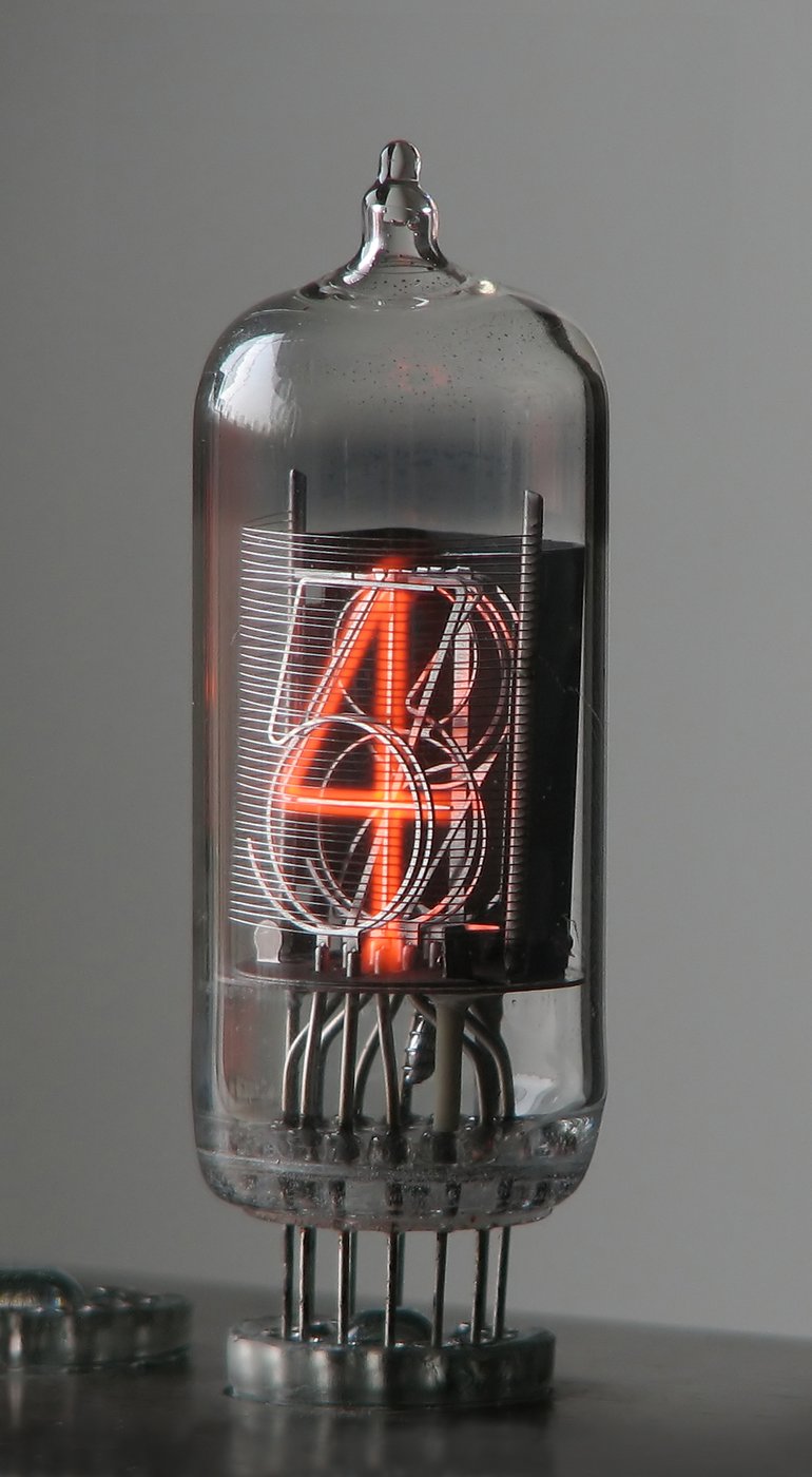
A nixie clock tells the time with glowing orange numerals suspended inside small glass tubes — each digit a sculpted wire filament that lights up by surrounding itself in a soft neon discharge when you pull it a couple of hundred volts below the tube’s anode. There are no pixels, no segments, no LCD haze: the figure “7” you see is a literal metal “7”, stacked one behind another with the other nine numerals, and the glow wraps the chosen one like cold fire. It is the warmest-looking display technology the twentieth century ever produced, it has been obsolete since about 1975, and it is for exactly that reason one of the most beloved things a hobbyist can build. A nixie clock combines a genuinely high-voltage power supply, a driver problem that has half a dozen elegant solutions, an ordinary microcontroller doing very ordinary timekeeping, and a glass-and-vapor display that is itself a small miracle of 1950s industrial design.
Note — this is the nixie technology overview. Specific nixie clocks Jeff owns or builds — their design, construction, and operation — are documented as their own deep dives in this technology’s
clocks/folder, one folder per clock, each avol*.mdseries with a Design → Building → Running spine. This volume series covers the technology in general; the per-clock dives go deep on individual units.
This eleven-volume reference covers the nixie clock at depth — the glow-discharge physics of the tube, the high-voltage supply that lights it, the several ways to drive the digits, the timebase and counting logic, a complete worked build from the owner’s own design files, the buy-a-kit and buy-a-finished-clock options, the projects collected in this hub (including a clock driven entirely by relays, and a cryptography-themed “Covert Bombe” concept), the enclosure and steampunk treatment, the safety discipline the ~170 V supply demands, and a laminate-ready cheatsheet. It is written for an experienced maker with an electronics bench, a soldering iron, and the patience to wire a tube that costs more than the board it sits on.
1.1 What a nixie clock actually is
Strip away the romance and a nixie clock is four subsystems wired together — the same four every digital clock has, but with one of them replaced by something gloriously anachronistic:
- The nixie tubes themselves — cold-cathode, neon-filled glow-indicator tubes (Burroughs coined the name Nixie, reputedly from the tube designation “NIX I,” Numeric Indicator eXperimental). Each tube holds a fine wire anode mesh in front and a stack of ten cathodes, each bent into the shape of a numeral 0–9 (and often an eleventh cathode for a decimal point). Light a cathode and that numeral glows; the depth of the stack is what gives a nixie its characteristic three-dimensional look (Vol 2).
- A high-voltage supply — the tube will not strike until the anode-to-cathode voltage exceeds its ignition (strike) voltage, typically around 170 V, and it needs the supply to sit comfortably above that. Almost every clock generates that rail with a small boost or flyback converter stepping up 5–12 V (Vol 3). This is the dangerous part: ~170–200 V DC behind a filter capacitor that stays charged after you unplug it.
- The digit drivers — something has to connect the chosen cathode of each tube to ground while withstanding the full anode voltage on the nine cathodes it is not lighting. The classic answer is the 74141 / K155ID1 BCD-to-decimal high-voltage driver; the modern answers are high-voltage shift registers (HV5622-class) and discrete high-voltage transistors (Vol 4).
- A timebase and counting logic — a microcontroller (or, in one collected project, a rack of relays) keeps the time from a crystal, an RTC chip, or the mains frequency, and updates the digits once a second (Vol 5).

The thing that makes a nixie clock a project rather than a purchase is that three of those four subsystems are easy and one is not. Timekeeping is a solved problem; a $2 RTC holds the time. The display is bought, not built — you source the tubes. But the high voltage and the digit driving sit right at the intersection of “interesting” and “can hurt you,” and that is where this series spends most of its pages.
1.2 A one-paragraph history
The nixie tube was introduced by Burroughs Corporation in 1955 (the trademark “Nixie” attached to a tube the Haydu brothers had been developing), and for two decades it was the way to put a readable decimal digit on an instrument — voltmeters, frequency counters, calculators, lab gear, and the occasional clock all glowed nixie orange through the 1960s. The Soviet electronics industry produced its own prolific family, the IN- series (ИН-12, ИН-14, ИН-18 and kin), which is why the cheapest and most plentiful tubes on the surplus market today are Russian. The technology was killed not by any flaw but by the seven-segment LED (and then the LCD), which were cheaper, lower-voltage, and solid-state; mass nixie production wound down by the mid-1970s. The tubes never fully died, though — a steady hobbyist demand kept new-old-stock (NOS) tubes changing hands, and around the 2000s the microcontroller nixie clock became a signature maker project. Today there is a healthy ecosystem: kit vendors (PV Electronics, GRA&AFCH), a celebrated maker of new, hand-built tubes and finished clocks (Dalibor Farný), and an endless supply of open-source board designs. The full history is told in Vol 2.
1.3 The ways to get a nixie clock
There is no single “the” nixie clock — there is a spectrum of paths from “open the box and plug it in” to “wire a chassis full of relays so the clock counts time with no microcontroller at all.” This hub recognizes six first-class paths, and the rest of the series is organized so that whichever one you choose, there is a volume that goes deep on it.
Table 1 — 1.3 The ways to get a nixie clock
| # | Path | Effort | Cost | Covered in |
|---|---|---|---|---|
| 1 | Buy a finished art clock (Dalibor Farný-class) | none | $$$$ | Vol 7 |
| 2 | Buy a kit and solder it (PV Electronics, GRA&AFCH) | low–medium | $$ | Vol 7 |
| 3 | Buy a cheap AliExpress kit / board + source your own tubes | low | $ | Vol 7 |
| 4 | Build the ATMega Cool Nixie Clock from the owner’s board + parts | medium | $$ | Vol 6 |
| 5 | Build the Relay Nixie Clock — no microcontroller, relay logic | very high | $$ | Vols 5, 8 |
| 6 | Design from scratch — your own PCB, your own firmware | very high | $ | Vols 3–6 |
Path 4 is the worked example throughout the engineering volumes: the hub holds a complete design for an ATMega-based clock driving ZM1210 tubes through 74141 drivers and 74HC595 shift registers, with schematic, PCB gerbers, and firmware all on disk (Vol 6). Path 5 is the novelty that makes this collection special — a clock that counts seconds, minutes, and hours using nothing but electromechanical relays (Vol 8).
1.4 Decision tree — which path is right for this build
Work top-down; stop at the first “yes.”
- Do you want a flawless nixie clock on the shelf this week, you value the object as craft, and budget is no object? → Path 1, a finished Dalibor Farný (or comparable) clock. Go to Vol 7.
- Do you enjoy soldering and want a well-documented, supported kit with tubes included? → Path 2, a PV Electronics or GRA&AFCH kit. Vol 7, then Vol 10 (safety) before first power-up.
- Is your budget tight and you don’t mind sourcing tubes and debugging terse instructions? → Path 3, an AliExpress kit/board + surplus IN-14s. Vol 7 for the board, Vol 2 to choose tubes, Vol 10 before you energize it.
- Do you want to build the design the owner of this hub can support directly, with full schematic, PCB, and firmware in hand? → Path 4, the ATMega Cool Nixie Clock. Vol 6, with Vols 3 and 4 as the engineering reference.
- Do you want a clock with no microcontroller — pure electromechanical logic, ticking and clicking? → Path 5, the Relay Nixie Clock. Vol 5 for the counting logic and Vol 8 for the project.
- Do you want to design your own board and write your own firmware? → Path 6. Vols 3–6 are the engineering reference you will live in.
Whatever the path, Vol 10 (safety) is mandatory reading before the first power-up — the anode supply runs at ~170–200 V DC and holds a dangerous charge after the clock is unplugged.
1.5 The tubes — a first orientation
You cannot choose a clock without choosing a tube, so here is the orientation the rest of the series builds on. Nixie tubes are sorted first by viewing direction and then by size and origin:
- Side-view (the iconic look) — the numerals stand upright and you read them through the side of the tube. The Soviet IN-14 (~18 mm digit height) is the most popular clock tube in the world: plentiful, cheap, NOS by the thousands. The IN-18 is the giant (~40 mm), prized and pricey. The Western Burroughs B-5092 and the Telefunken/Philips ZM1100-series are the classic side-view tubes of the original era.
- End-view (top-read) — you look down the axis of the tube at the numeral stack. The IN-12 is the common end-view Soviet tube (often mounted flat on a PCB); the ZM1210 used in this hub’s worked build is an end-view Telefunken tube with a 15.5 mm digit height.
- Small / sub-miniature — the IN-16 and IN-17 are tiny tubes for compact clocks.
All of these are cold-cathode tubes — there is no heated filament boiling off electrons the way a vacuum tube or a CRT cathode does. The glow is a self-sustaining neon glow discharge struck purely by the electric field, which is why a nixie runs cool and lasts for tens of thousands of hours. The physics is Vol 2’s subject; the one fact to carry forward is that the discharge has a strike voltage (higher, to ignite) and a lower maintaining voltage (to keep it lit), and the whole art of driving nixies lives in that gap.
1.6 What the owner already has collected
Four projects are catalogued in this subproject’s 02-inputs/, and they map neatly onto
the volume plan:
- ATMega Based Cool Nixie Clock — a complete AVR/ATMega design driving ZM1210
tubes via 74141 BCD drivers fed by 74HC595 shift registers. The hub holds the
schematic (a multiplexed variant too), the ATMega manual, the 74HC595 datasheet, PCB
gerbers (
nixiepcb.zip), and thenix-in-17firmware. This is the worked build of Vol 6. - Awesome / Lamina Nixie Clock — a reference design (PDF) for a clean, modern nixie clock; a comparison point and a source for the buy/kit discussion (Vols 7, 8).
- Relay Nixie Clock — a nixie clock driven entirely by relay logic, no microcontroller anywhere. The hub holds the relay-logic project notes and the RL1200 relay datasheet/schematic. A genuine novelty, covered in Vols 5 and 8.
- The Covert Bombe — Enigma — an aesthetic/themed concept: a display dressed as a WWII Enigma/Bombe cryptography machine, with a large reference image set (Bombe, Enigma, and Tatjana van Vark’s modern crypto machines) to seed the design. An inspiration project for the enclosure volume (Vol 9).
1.7 How this series is organized
The series moves from principle to practice to project to polish:
- Principle (Vols 2–5) — how the tube works, then each subsystem in turn (the HV supply, the digit drivers, the timebase and logic). Read these to understand any nixie clock.
- Projects (Vols 6–8) — the owner’s ATMega build start to finish, the buy-it options, and a walk-through of every collected project including the relay clock.
- Polish (Vols 9–11) — the enclosure, finishing, and themed/steampunk treatment; the safety discipline; and the laminate cheatsheet and glossary.
1.7.1 Volume-by-volume index
Table 2 — 1.7.1 Volume-by-volume index
| Vol | Title | Read it for |
|---|---|---|
| 1 | Overview & Decision Tree | (this volume) — the map and the path choice |
| 2 | How a Nixie Tube Works | glow-discharge physics, tube anatomy, families, poisoning, lifetime |
| 3 | The High-Voltage Supply | generating and taming the ~170-200 V anode rail |
| 4 | Driving the Digits | 74141/K155ID1, HV shift registers, discrete drivers, multiplexing, dimming |
| 5 | Timebase & Logic | RTC, crystal vs mains reference, MCU firmware — and the relay-logic alternative |
| 6 | Build It Yourself | the owned ATMega Cool Nixie Clock, schematic → BOM → PCB → firmware → calibration |
| 7 | Buy a Kit or Finished Clock | Dalibor Farný, PV Electronics, GRA&AFCH, AliExpress; tube sourcing, trade-offs |
| 8 | The Collected Projects | ATMega Cool, Lamina, the Relay clock, the Covert Bombe/Enigma concept |
| 9 | Enclosure, Finishing & the Themed/Steampunk Treatment | cases, tube mounting, the covert-Bombe theme, steampunk |
| 10 | Safety | HV discipline for nixie supplies, NOS tube handling and testing |
| 11 | Cheatsheet & Glossary | pinouts, driver truth tables, supply formulas, vendor URLs, A-Z terms |
1.8 What this series is — and is not
It is a build-and-understand reference for cold-cathode nixie display clocks, grounded in a complete design the owner has on disk and the projects collected in this hub.
It is not a substitute for the original designers’ documentation when you build a specific kit — Vols 6 and 7 point you at the canonical board files and reproduce the critical data (pinouts, driver truth tables, supply targets), but you should build with the original documents open alongside. Nor is it a guide to the other cold-cathode display families — dekatron counting tubes, Panaplex/Pixie seven-segment gas-discharge panels, or VFD (vacuum-fluorescent) displays — except where they illuminate the nixie by contrast. Those are different technologies with their own quirks, noted in Vol 2 but not covered in build depth.
1.9 Safety, stated once up front
Every path in this series involves an anode supply that produces roughly 170 to 200
volts of direct current, generated by a switching converter and stored behind a filter
capacitor that stays charged after the clock is unplugged. This is well below the
kilovolts of the hub’s scope/CRT clocks, but it is well above the threshold where a shock
across the chest can stop a heart, and the small filter capacitors common in these
supplies can deliver a memorable and dangerous jolt. The full discipline — discharge
procedure, the one-hand rule, never working on a powered board, bleeder resistors, and
the special care NOS tubes deserve — is in Vol 10 and the hub-wide _shared/safety.md.
Read it before you energize anything. Throughout this series, a ⚠ marks a step where
those rules are in force.
1.10 Photo policy
Photographs in this series come from three sources, credited in every caption: the owner’s own build photos and reference collection; license-clean images from Wikimedia Commons / Openverse fetched through the project’s Photo Helper (with the full attribution line reproduced verbatim); and, for diagrams, hand-authored SVG. Figures that have not yet been sourced are simply absent. No images are scraped from arbitrary copyrighted web pages.
1.11 References (Vol 1)
- ATMega Based Cool Nixie Clock — designer files (ZM1210 display schematic, multiplexed
schematic, 74HC595 datasheet, ATMega manual, PCB gerbers
nixiepcb.zip,nix-in-17firmware). Held in02-inputs/ATMega Based Cool Nixie Clock/. - Awesome / Lamina Nixie Clock reference. Held in
02-inputs/Awesome Nixie Clock/. - Relay Nixie Clock — relay-logic project notes and the RL1200 relay datasheet/schematic.
Held in
02-inputs/Relay Nixie Clock/. - The Covert Bombe / Enigma reference image sets. Held in
02-inputs/The Covert Bombe - Enigma/. - Burroughs Corporation, Nixie tube introduction (1955); the “Nixie” trademark history.
- Soviet IN-series (ИН-12 / ИН-14 / ИН-18) and Telefunken/Philips ZM-series tube datasheets.
_shared/safety.md(hub-wide HV safety baseline) and_shared/deep_dive_protocol.md.
Comments (0)