TIX · Volume 5
Timebase, Randomisation & Firmware
How a TIX clock keeps the time, re-rolls the lit cells every minute, and what the two collected builds run on the metal
Everything else in this series is plumbing for one small program. The display (Vol 3)
is a grid of bare LEDs; the driver (Vol 4) is a way to light any chosen subset of them
fast enough to look continuous; but which cells to light, and when to change them,
is decided entirely in firmware — and that firmware carries one job no other clock in
this hub has. A nixie clock that knows it is 16:24 has only to put a 6 on one tube
and a 4 on the next; there is exactly one right answer and it never changes until the
minute does. A TIX clock that knows it is 16:24 must light one of three yellow
cells, six of nine red, two of six blue, and four of nine green — and there
are thousands of equally-correct ways to do that, so the firmware picks one at random,
and picks a fresh one every minute. This volume is the brain: the timebase that
holds the time, the randomiser that turns four digits into four scattered patterns,
and the two real firmwares — gweeds in BASCOM-AVR BASIC, ujjaldey in Arduino C++ —
that the collected builds actually run.
Two clocks tick inside this volume and they must not be confused. One is the timebase: the slow, accurate, once-a-second (or once-a-minute) advance of real wall-clock time. The other is the refresh: the fast, kHz-ish multiplex scan of Vol 4 that keeps the already-chosen pattern visible. The randomiser sits between them, fired once a minute by the timebase, handing a new pattern down to the refresh. Keep those three rates — per-second timekeeping, per-minute re-roll, per-millisecond refresh — separate in your head and the whole firmware falls into place.

5.1 The timebase — what holds the time
A clock is only as good as the thing counting its seconds. A TIX clock has three plausible timebases, and the two collected builds sit at opposite ends of the range, with a clear upgrade beyond both.
5.1.1 Three options, two builds
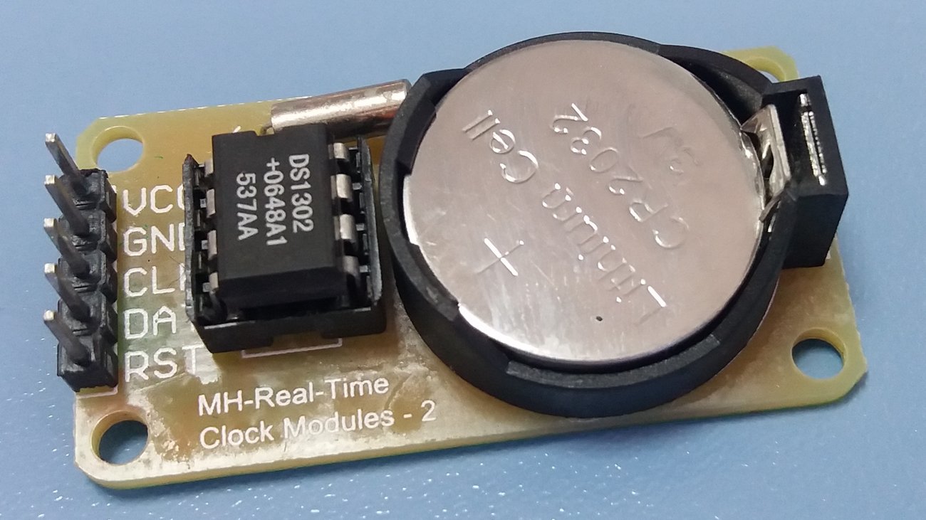
- A bare MCU crystal (gweeds DIY TiX). The gweeds build keeps time on the AVR’s own crystal oscillator — the same oscillator that clocks the processor. There is no separate real-time-clock chip in the schematic. The firmware configures a hardware timer to interrupt at a known rate, counts those interrupts into seconds, minutes and hours, and that is the clock. It is the cheapest possible timebase — you were going to pay for the crystal anyway — but it has two costs: it is not very accurate, and it stops dead when the power goes off. Pull the USB cable and the clock forgets the time completely; plug it back in and it starts from whatever the firmware initialises to, waiting for you to set it with the buttons.
- A DS1302 RTC with backup cell (ujjaldey uTixClock). The uTix build adds a dedicated DS1302 real-time-clock module: a small chip that counts the calendar on its own low-power oscillator, with a backup battery so it keeps counting while the main 5 V is off. ujjaldey’s own pitch is “Never forgets the time — even if you power it off.” The Arduino reads the time from the DS1302 over the chip’s three-wire interface; the AVR is now free of timekeeping duty and merely asks the RTC what time it is. This is the right shape for a clock — timekeeping belongs in a part designed for it.
- A DS3231 RTC (the upgrade path). The DS1302 keeps the time across a power cut but it is not accurate — it is an ordinary crystal RTC with no temperature compensation. The standard upgrade, used across this hub, is the DS3231: a temperature-compensated crystal oscillator (TCXO) RTC rated at ±2 ppm. It is a near drop-in (a different library, an I²C bus instead of the DS1302’s three wires) and it is the single biggest accuracy improvement you can make to either build. Vol 6 notes it as the recommended substitution.
5.1.2 What the accuracy numbers actually mean
Oscillator accuracy is quoted in parts per million (ppm) — microseconds of error per second, equivalently. To turn ppm into wall-clock drift, multiply by the length of the interval:
seconds of error = ppm × 1e-6 × seconds_in_interval

per day   = ppm × 1e-6 × 86 400  s  ≈ ppm × 0.0864  s
per year  = ppm × 1e-6 × 31 557 600 s ≈ ppm × 31.6   s
Worked for the three timebases:
Table 1 — Worked for the three timebases
| Timebase | Typical accuracy | Error per day | Error per year | Survives power-off? |
|---|---|---|---|---|
| Bare MCU crystal (gweeds) | ~10–50 ppm | ~1–4 s/day | ~5–26 min/yr | No — loses time |
| DS1302 RTC (uTix) | tens of ppm, uncompensated1 | a few s/day → minutes/month | many minutes/yr | Yes (backup cell) |
| DS3231 RTC (upgrade) | ±2 ppm (TCXO) | ~0.17 s/day | ~1 min/yr | Yes (backup cell) |
Two things fall out of the table. First, the gweeds crystal and the DS1302 are in the same ppm league for raw rate accuracy — a bare MCU crystal is not inherently worse at counting than a cheap RTC. The DS1302’s whole advantage is the backup cell: it keeps counting through a power cut, which the bare crystal cannot. Second, the DS3231 is in a different league entirely — an order of magnitude or more better than either — because it measures its own temperature and corrects for it, which is where most of a cheap crystal’s error comes from (oscillator frequency drifts with temperature). For a clock you glance at daily, a DS1302 losing a minute a month is a mild nuisance you re-set occasionally; a DS3231 losing a minute a year you can largely forget.
5.1.3 Power-loss behaviour, stated plainly
This is the practical difference a user feels:
- gweeds (bare crystal): unplug → time is gone. On next power-up the clock shows whatever the firmware boots to and must be re-set with the buttons (§5.4). Fine for a clock that lives on a powered desk; annoying if it shares a switched outlet.
- uTix (DS1302) and the DS3231 upgrade: unplug → the RTC keeps counting on its backup cell; on next power-up the firmware reads the correct current time straight from the chip and the display is right within a minute. The backup cell (a coin cell, or in the DS1302’s case a trickle-charged capacitor/cell) lasts months to years.

5.2 The randomiser — the logic unique to this technology
Here is the one piece of code a TIX clock has that no numeral clock needs. Once per minute the firmware knows the time as four digits; it must turn each digit into a scattered subset of lit cells of exactly that size, freshly chosen so the arrangement differs from last minute’s. Position carries no meaning (Vol 2), so the firmware is free to choose any subset — and that freedom is the whole visual personality of the clock.
5.2.1 The problem, precisely
For each of the four fields the firmware has:
n— the number of cells in the field (3, 9, 6, 9 for yellow/red/blue/green),k— the target count, i.e. the digit (0…n),
and it must produce a pattern that lights exactly k of the n cells, chosen
uniformly at random among all such patterns, re-rolled each minute. “Exactly k”
is non-negotiable — light k±1 and the clock is simply wrong. The randomness is what
makes it a TIX clock rather than a static count.
The collected sources describe the behaviour — random cells, re-rolled each minute, exactly the right count — but neither publishes its exact selection routine. The two algorithms below are the standard ways to meet that spec; treat them as how you would (and almost certainly how the builds do) implement it, not as a transcription of either author’s code.
5.2.2 Algorithm A — Fisher–Yates shuffle, then light the first k
The clean, constant-effort method. Keep an array of the field’s cell indices, shuffle it
with a Fisher–Yates shuffle, and light the first k entries. Because the shuffle is
uniform, every k-subset is equally likely, and it does exactly n−1 swaps regardless of
k.
# light exactly k of n cells, uniformly at random
function pickCells(n, k):
    idx = [0, 1, ..., n-1]            # the cell positions in this field
    for i from n-1 down to 1:         # Fisher–Yates shuffle
        j = randomInt(0 .. i)         # inclusive
        swap idx[i], idx[j]
    pattern = all-off
    for m from 0 to k-1:
        pattern[ idx[m] ] = ON        # light the first k of the shuffled order
    return pattern                    # exactly k bits set, position random
5.2.3 Algorithm B — rejection sampling (pick distinct cells until k are on)
The method most people reach for first: repeatedly pick a random cell; if it is already
on, pick again; stop when k are lit. Simple, and for the tiny fields here (n ≤ 9) the
wasted re-picks are negligible. It gets slow only when k is close to n (the last cell
is hard to hit) — for a 9-cell field showing 9 you would thrash — so a common refinement is
to light all cells and randomly turn off n−k of them when k > n/2. For TIX-sized
fields either form is instant.
function pickCells_reject(n, k):
    pattern = all-off
    lit = 0
    while lit < k:
        c = randomInt(0 .. n-1)
        if pattern[c] == OFF:
            pattern[c] = ON
            lit = lit + 1
    return pattern
Both algorithms share the same guarantee: exactly k cells end up lit, and which
k is uniform and fresh. Algorithm A is preferred when you want predictable timing;
Algorithm B is fine at this scale and reads more obviously.
5.2.4 Seeding the PRNG so the patterns actually differ
A pseudo-random generator started from the same seed produces the same “random” sequence every run — so a naïve build re-rolls the identical pattern after every reboot, or worse, shows the same arrangement for a given time every day. The fix is to seed the PRNG from something that changes:
- seed from the RTC seconds (or the full date-time) at start-up — different every power-on;
- or seed from analog noise on a floating ADC pin (
analogReadof an unconnected input) — the Arduino idiomrandomSeed(analogRead(A0)); - and let the generator free-run thereafter, so each minute’s re-roll draws the next values.
You do not need cryptographic randomness — only enough variation that a human never notices a repeat. Re-seeding once at boot is plenty; some builds also stir in the seconds value at each re-roll for extra variation. The point is purely aesthetic: the clock should never look like it is cycling.

5.3 Firmware structure of the two builds
Both firmwares do the same four things — keep time, compute counts, re-roll, refresh — but in different languages on different timebases, and it is worth seeing each shape.
5.3.1 gweeds — BASCOM-AVR BASIC on a bare AVR
The gweeds build is written in BASCOM-AVR, a BASIC dialect for Atmel AVRs, and ships as
source plus schematic and PCB in tixclock.zip. With no RTC chip, the firmware is the
clock: a hardware timer is configured to overflow at a known rate and its interrupt
service routine increments a seconds counter, rolling into minutes and hours. The main loop
does the display work and watches the set buttons. In shape:
' --- BASCOM-AVR, sketch of the structure (illustrative) ---
Config Timer1 = Timer , Prescale = ...      ' timer for the timebase
On Timer1 Tick_Isr                          ' ISR advances the clock
Enable Interrupts

Do                                          ' main loop
   If Minute_changed Then                    ' once-per-minute re-roll
      Compute_counts                         ' HH:MM -> k_yellow,k_red,k_blue,k_green
      Pick_random_patterns                   ' choose which cells (sec 5.2)
   End If
   Scan_matrix                               ' multiplex refresh (Vol 4), runs every pass
   Check_set_buttons                         ' hour/minute set inputs
Loop

Tick_Isr:                                    ' fires from Timer1
   Incr Tick : If Tick = Ticks_per_sec Then ...  ' seconds -> minutes -> hours
Return
The two timescales are explicit here: Scan_matrix runs on every pass of the loop
(the kHz refresh of Vol 4, scanning the transistor row/column matrix), while
Pick_random_patterns runs only when the minute rolls over. The timer ISR is the timebase;
the loop is everything else.
5.3.2 ujjaldey — Arduino C++ with a DS1302 RTC
The uTix build is Arduino C++ (developed in VS Code + PlatformIO; the Arduino IDE also
builds it), and the source lives in a public Git repo. Timekeeping is handed entirely to the
DS1302 via an Rtc library (RtcDS1302), so loop() never counts seconds itself — it
asks the RTC. The setup follows the library’s standard validity dance, comparing the RTC
against the firmware’s compile time:
void setup() {
  Serial.begin(9600);
  Rtc.Begin();
  RtcDateTime compiled = RtcDateTime(__DATE__, __TIME__);   // build timestamp

  if (!Rtc.IsDateTimeValid()) {                 // power-lost / low battery?
    // Rtc.LastError() tells you why; re-set to the compile time
    Rtc.SetDateTime(compiled);
  }
  if (!Rtc.GetIsRunning()) Rtc.SetIsRunning(true);  // make sure the oscillator runs
  RtcDateTime now = Rtc.GetDateTime();
  if (now < compiled) Rtc.SetDateTime(compiled);    // never behind the build time
  randomSeed(analogRead(A0));                        // seed the randomiser (sec 5.2.4)
}
And the loop reads the time, computes the four counts, re-rolls on the minute boundary, reads the LDR for brightness, and runs the scan:
void loop() {
  RtcDateTime now = Rtc.GetDateTime();          // 24-hour time from the DS1302
  if (now.Minute() != lastMinute) {             // once-per-minute re-roll
    lastMinute = now.Minute();
    computeCounts(now.Hour(), now.Minute());    // -> kY, kR, kB, kG
    pickRandomPatterns();                        // choose which cells (sec 5.2)
  }
  int light = analogRead(LDR_PIN);              // ambient light...
  setBrightness(light);                          // ...sets PWM / scan duty (Vol 4)
  scanMatrix();                                  // multiplex refresh via the 595s (Vol 4)
}
Same two timescales as gweeds: scanMatrix() every pass, pickRandomPatterns() only on the
minute. The differences are that the DS1302 owns the time (so a reboot recovers it), the
time is in 24-hour form from now.Hour()/now.Minute(), and the LDR auto-dim is read in
firmware and fed to the driver as a brightness/duty value (Vol 4 covers how that becomes
actual brightness).
5.3.3 Computing the four counts
Trivially, the counts are the digits of the 24-hour time:
kYellow = hour  / 10        # tens of hours   (0..2)  -> 3-cell field
kRed    = hour  % 10        # units of hours  (0..9)  -> 9-cell field
kBlue   = minute / 10       # tens of minutes (0..5)  -> 6-cell field
kGreen  = minute % 10       # units of minutes(0..9)  -> 9-cell field
Each of these k values is then fed to the randomiser of §5.2 for its field. That is the
entire bridge from “what time is it” to “which cells light.”
5.4 Time-setting, the midnight quirk, and UX
5.4.1 Setting the time — two very different stories
- gweeds has physical set buttons. Because the bare crystal forgets the time on every power-off, the gweeds build needs a way to set it, and it has one: lathe-turned set buttons wired to MCU inputs, read in the main loop. Press to advance hours/minutes; the firmware writes the new value into its software clock. Conventional, and necessary given the timebase.
- uTix, as shipped, has no button set-UI. This is a real and slightly surprising
limitation of the published uTix build: there is no on-clock way to set the time by
button. Instead the time is established two ways: at compile time, via the
RtcDateTime(__DATE__, __TIME__)trick above — the firmware bakes in the moment it was built and, if the RTC is invalid or behind, sets the DS1302 to that — and over the serial link while connected. ujjaldey lists “Adjust date and time” as a planned future feature, not something the shipped firmware does. In practice this is tolerable because the DS1302 is battery-backed: you set it once (by flashing a fresh build at the right moment, or over serial) and the backup cell carries it from then on. But it means you cannot nudge the clock by a minute without a computer — a genuine rough edge, and the obvious first improvement to make (a two-button hour/minute set, exactly as gweeds has).
5.4.2 The midnight 00:00 blank quirk
A consequence of the count encoding bites at exactly one time of day. At 00:00, all four digits are zero, so all four counts are zero, so no cells are lit at all — the display goes completely blank for the whole first minute of the day (and again, the firmware will re-roll an all-dark “pattern” because zero-of-n is, correctly, nothing lit). The clock is not broken; it is correctly showing four zeros. But to a viewer it looks dead, and it is indistinguishable from a power failure.
Ways to fix or soften it, none in the shipped builds:
- A “zero” indicator. Light a small dedicated marker (a separate LED, or a reserved corner cell) whenever a field’s count is zero, so “this field reads 0” is visibly zero rather than absent. This is the cleanest fix and generalises to any all-dark field, not just midnight.
- A heartbeat. Blink one cell, or briefly sweep the panel, when the whole display would otherwise be blank, so the clock visibly says “I’m alive and it’s midnight.”
- A 12-hour face. Switching the tens-of-hours field to a 12-hour scheme does not remove the problem (12:00 and 00:00 both still hit all-zero minutes), so this is not actually a fix — note it only to dismiss it.
The first option is what this series recommends if you build your own: a reserved zero-marker cell per field costs four LEDs and makes the encoding honest at midnight. It is flagged here because neither collected build addresses it — both go dark at 00:00.
5.5 How this volume connects
The randomiser of §5.2 produces a 27-bit “which cells are on” pattern once a minute; that pattern is the input to the driver of Vol 4, which scans it onto the LED matrix thousands of times a second (transistor matrix in gweeds, 74HC595 chain in uTix) and applies the LDR brightness from §5.3.2. What the viewer then does with it — count, don’t read position — is Vol 2. The timebase of §5.1 is the part the viewer never sees but most often curses: it is why the gweeds clock needs re-setting after a power cut and the uTix clock does not. Vol 6 puts all of this on a board.
5.6 References (Vol 5)
- DIY TiX Clock by gweeds (Guido Seevens), Instructables, 2011 — BASCOM-AVR firmware on a
bare AVR (timer-based software clock, no RTC), physical lathe-turned set buttons,
transistor-multiplexed matrix. Source/schematic/PCB in
tixclock.zip. Held in02-inputs/DIY-TiX-Clock.pdf. Source: http://www.instructables.com/id/DIY-TiX-Clock/. - uTixClock by ujjaldey, Instructables — Arduino C++ (VS Code + PlatformIO) on an Arduino
Nano, DS1302 battery-backed RTC via an
RtcDS1302library, LDR auto-dim, 24-hour time, no button set-UI in the shipped build (time set via compile-time__DATE__/__TIME__and serial; “Adjust date and time” listed as a planned feature), blank at 00:00. Public Git source. Held in02-inputs/UTixClock.pdf. Source: https://www.instructables.com/id/UTixClock/. - Vol 4 (the multiplex scan and LDR dimming this firmware drives) and Vol 2 (the count encoding the randomiser serves) in this series.
Footnotes
-
The DS1302 is a low-cost trickle-charge RTC with no temperature compensation; its rate accuracy is set by an ordinary 32.768 kHz crystal and load, so real-world drift is commonly quoted in the minutes per month range — adequate for a casual desk clock, an order of magnitude worse than the temperature-compensated DS3231 (±2 ppm, ≈1 min/yr). The gweeds bare AVR crystal is in a similar ppm class but, unlike either RTC, has no backup and loses the time entirely on power-off. ppm-to-drift conversions in §5.1.2 use 86 400 s/day and 31 557 600 s/year. ↩
Comments (0)