TIX · Volume 3
The LED Display
The light-emitting layer: 5 mm LEDs, the 3/9/6/9 colour fields, and why round LEDs read as squares
Everything a TIX clock says it says with light. Strip away the timebase, the randomiser, and the drive electronics — all of which arrive in the next two volumes — and what is left is the thing on the shelf: a panel of small coloured lamps, some lit and some dark, that a person counts. This volume is about that panel as a physical, light-emitting layer — the LEDs themselves, how they are grouped into the four colour fields, why the cells look square when the parts are round, and what makes the face easy or hard to read. It deliberately stops at the glass: how the LEDs are turned on (the multiplexed matrix, the shift registers, the current-limiting) is Vol 4, and how the bare LEDs are diffused into clean squares behind a dark window is Vol 8. Here we establish the display’s anatomy and the reasons behind every choice, and we hand the two hardest questions — matched brightness and the diffuser stack — forward to the volumes that own them.
The good news for the builder is that this is forgiving territory. Both collected builds use the most ordinary part in the catalogue — the 5 mm through-hole LED — in the most ordinary way, twenty-seven of them, and the whole display runs at 5 V with a resistor in series. There is no exotic emitter, no addressable strip, no high voltage. The interest is not in the component but in the arrangement: four counts the eye must read at a glance, separated by colour, sized so the largest digit always fits, and diffused so each lit LED becomes a soft square rather than a hot dot.
3.1 The emitter: a plain 5 mm through-hole LED
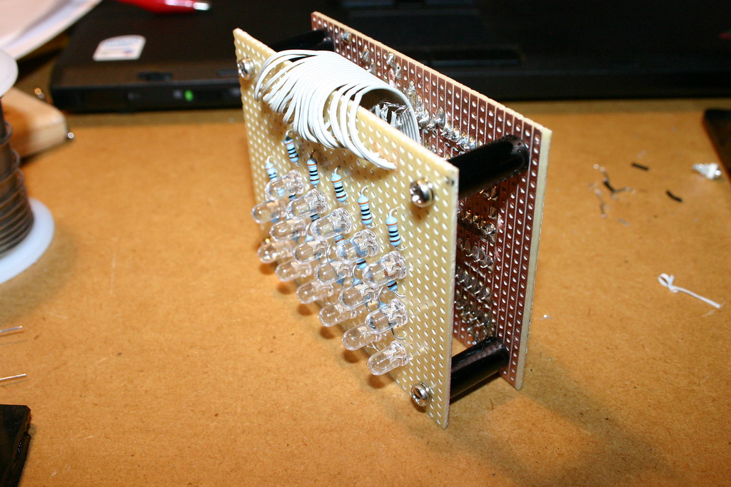
Both worked builds in this hub light the face with 5 mm through-hole LEDs — the classic two-legged, round-domed indicator LED that has been the default hobby light for decades. The ujjaldey uTixClock is explicit about it: twenty-seven 5 mm LEDs, 3 yellow, 9 red, 6 blue, 9 green, on a Veroboard display panel.1 The gweeds DIY TiX likewise uses 5 mm LEDs, mounted on a board that the build sandwiches behind a reflector grid and a paper diffuser.2 Neither source publishes exact LED part numbers (manufacturer, bin, or precise wavelength), so this volume treats the LEDs as generic 5 mm indicators in four colours and says so plainly wherever a specific number would otherwise be tempting.
A 5 mm LED is well-suited to this job for unglamorous reasons. It is cheap by the bag, its ~5 mm body sits on a comfortable grid pitch for counting (§3.3), its domed top is bright enough to drive a diffuser without straining, and its long legs make it easy to lift off the board on stand-offs and to wrap with a reflector — the gweeds build even notes cutting holes in a tinfoil reflector around the legs so the light is thrown forward rather than lost sideways.2 The dome shape, which would be a liability if you wanted a flat uniform emitter, stops mattering the moment a diffuser goes in front: the diffuser is what the eye sees, not the LED (§3.4).
One emitter property does matter, and it is the one beginners overlook: an LED’s forward voltage depends on its colour, and that has consequences for brightness. We take that next, because it is the single most important electrical fact about the display layer — and the one this volume hands forward to Vol 4.
3.2 Colour, forward voltage, and the matched-brightness problem
3.2.1 Why each field is one colour
The four fields are read at a glance, and the eye needs help keeping them apart. Colour is that help. Both collected builds assign one colour per field — yellow to the tens-of-hours, red to the units-of-hours, blue to the tens-of-minutes, green to the units-of-minutes — so that the four counts group themselves without any lines, boxes, or gaps doing the work.12 When you glance at the face you are not parsing a single field of twenty-seven identical dots; you are seeing four coloured clusters, and your eye counts within each cluster. Take the colour away — twenty-seven white LEDs in a row — and the reading task gets markedly harder, because now you must first mentally partition the panel into 3/9/6/9 before you can count. Colour does that partitioning for free, instantly, pre-attentively. The specific colour-to-field mapping is a convention of these builds, not a law; what matters is that adjacent fields differ enough to read apart (§3.5).
3.2.2 Forward voltage varies by colour
Here is the fact that quietly governs the electrical design. The voltage an LED drops when it conducts — its forward voltage, V_f — is set by the semiconductor’s band-gap, which is different for each emission colour. As general electronics knowledge (not something either source measures), typical 5 mm indicator LEDs fall in these ranges:
Table 1 — source measures), typical 5 mm indicator LEDs fall in these ranges
| Colour | Typical V_f | Note |
|---|---|---|
| Red | ~1.8–2.2 V | lowest band-gap of the common colours |
| Yellow | ~1.8–2.2 V | similar to red |
| Green (traditional) | ~2.0–2.4 V | older GaP/AlGaP “yellowish” green |
| Green (modern InGaN) | ~2.8–3.4 V | bright “pure” green; same chemistry as blue |
| Blue | ~2.8–3.4 V | high band-gap |
Treat these as typical ranges, not as values for any particular part in either build — the sources do not specify V_f, and a real green LED could sit anywhere from ~2.0 V to ~3.4 V depending on whether it is an old-style or a modern InGaN device. The point is the spread: a red and a blue LED on the same 5 V rail do not drop the same voltage, sometimes differing by more than a volt.
3.2.3 Why that spread is a matched-brightness problem
Drive two differently-coloured LEDs through the same series resistor from the same rail and they will not carry the same current. Current through a series resistor is set by the voltage left over after the LED takes its drop:
I = (V_supply − V_f) / RWith a 5 V rail and, say, a 33 Ω resistor (the value the uTixClock uses on three of its fields1):
Red   LED, V_f ≈ 2.0 V:  I = (5.0 − 2.0) / 33 ≈ 91 mA   (per-LED; see Vol 4 on duty cycle)
Blue  LED, V_f ≈ 3.2 V:  I = (5.0 − 3.2) / 33 ≈ 55 mA
The blue LED gets barely over half the current of the red one from an identical resistor. (Those raw figures are instantaneous matrix-on currents, not steady DC — in a scanned display each LED is lit only a fraction of the time, which is exactly why the numbers can look high; that is Vol 4’s department.) Worse, current and perceived brightness are not the same thing: the human eye is most sensitive in the green-yellow midband and least sensitive at the blue and deep-red ends, so even at equal current a blue LED can look dimmer than a green one of the same rated output, and a red can look punchier than its milliamps suggest. Stack the two effects — unequal current from a shared resistor and unequal eye sensitivity — and a naively-built TIX display can show a vivid red field next to a washed-out blue one, which sabotages the very at-a-glance reading the colours were meant to enable.
The fix is to size the series resistor per colour (and, in a multiplexed design, to weigh duty cycle as well) so that every field lands at a similar perceived brightness. The uTixClock hints at exactly this asymmetry in its bill of materials — three 33 Ω resistors and one 10 kΩ, i.e. not one global value — though the source does not spell out which resistor serves which colour.1 The full treatment of resistor selection, per-colour matching, and the duty-cycle interaction belongs to the drive volume; this volume’s job is only to flag that the problem is born in the display layer, the instant you choose four different colours, and is carried to Vol 4 to solve.

3.3 The field grid: 3 / 9 / 6 / 9 as sub-grids of cells
3.3.1 The cell counts and why they are what they are
The face holds four fields, each sized to the largest digit it must ever display, read
left to right as a 24-hour HH:MM:
Table 2 — left to right as a 24-hour HH:MM
| Field | Colour | Cells | Digit | Range |
|---|---|---|---|---|
| 1 | yellow | 3 | tens of hours | 0–2 |
| 2 | red | 9 | units of hours | 0–9 |
| 3 | blue | 6 | tens of minutes | 0–5 |
| 4 | green | 9 | units of minutes | 0–9 |
That is the canonical 3 / 9 / 6 / 9 layout, 27 LEDs in total.1 Each count is the smallest that still holds the field’s maximum digit: the tens-of-hours never exceeds 2, so three cells are plenty; the tens-of-minutes never exceeds 5, so six; the two units fields must reach 9, so nine each. There is no slack and no waste — a field with more cells than its maximum digit would simply have LEDs that never light, and a field with fewer could not display its largest value.
3.3.2 Arranged as small rectangular sub-grids
The cells of a field are not strewn at random positions (the firmware does that with which cells are lit — §3.6); they sit on a tidy rectangular sub-grid so the eye can take in the whole field at once. In the uTixClock photos the fields read as compact blocks: the 9-cell red and 9-cell green fields as 3 × 3 sub-grids, the 6-cell blue as a 2 × 3 (or 3 × 2), and the 3-cell yellow as a 1 × 3 (or 3 × 1) strip.1 The exact orientation — whether blue is two rows of three or three rows of two, whether yellow runs across or down — is not fixed by the source, and there is no reason it must be: because position carries no information, a field can be laid out in whatever rectangle packs neatly into the case, so long as the cells are countable. A 3 × 3 block is the natural shape for nine; six and three have a couple of equally valid rectangles each.
The whole panel, then, is four little rectangles of coloured dots — a 1 × 3 (or 3 × 1) yellow, a 3 × 3 red, a 2 × 3 blue, a 3 × 3 green — set side by side with clear gaps between fields. Twenty- seven cells, four counts, one glance.

3.3.3 Spacing for a clean count
A field exists to be counted, and counting fails at both extremes of spacing. Pack the LEDs too tightly and two adjacent lit cells smear into one blob behind the diffuser — you lose count. Space them too loosely and the field sprawls, the four clusters stop reading as four, and the eye has to hunt. The 5 mm body sets a comfortable natural pitch: cells spaced roughly a body-width or so apart, with a visibly larger gap between fields than within a field, so the colour blocks stay distinct. This within-field-tight, between-field-loose spacing is part of what makes the colour grouping (§3.2.1) work; it is also one of the jobs the cell-grid wall does mechanically (§3.4, and fully in Vol 8).
3.3.4 The 12-hour alternative and other layouts
The 3/9/6/9 face shows 24-hour time, which is why the tens-of-hours field needs three cells (it must reach 2). A 12-hour face never shows a tens-of-hours above 1, so that field collapses to a single cell: the layout becomes 1 / 9 / 6 / 9, twenty-five LEDs.3 That one-cell field is a slightly awkward thing to “count” — it is either off (hours 1–9, or 10–12 read as 10/11/12 with the units field) or on — but it is the standard reduction and it saves two LEDs and a little width. Beyond the 12-vs-24 choice, a designer is free to make other layout decisions the sources do not prescribe: the sub-grid orientations (§3.3.2), the colour-to-field mapping (§3.2.1), the physical pitch, even — for someone designing from scratch (Vol 1, Path 4) — swapping the driven matrix for addressable “smart” LEDs. The encoding does not care; it only needs four countable fields of the right sizes.
3.4 Why round LEDs read as squares
The signature TIX look is a grid of crisp, evenly-lit squares — and that is the one thing about the display that is not a property of the LEDs at all. A 5 mm LED is round, with a domed top and, undiffused, a bright hot-spot at its centre and a fall-off toward the edge. Left bare, a TIX field looks like what it is: a cluster of round glowing dots. The square comes entirely from the diffusion stack in front of the LEDs.
The mechanism, in brief (Vol 8 builds it properly): each LED sits in its own square-walled cell — in the gweeds build, a reflector grid cut from a square-celled office-light louvre; in the uTixClock, a square-cell grid printed into the PLA+ case.12 The cell walls box each LED’s light into a square footprint and stop it bleeding into its neighbours. A diffuser layer — draughtsman’s tracing paper in the gweeds build, a transparent/translucent paper in the uTixClock — sits over the cells and spreads each LED’s hot-spot into an even glow that fills its square. Finally a dark window — smoked perspex (gweeds) or black acrylic (uTixClock) — covers the whole face, hiding the unlit cells and the machinery and lifting contrast (§3.5). The eye, looking at the assembled stack, sees a softly glowing square wherever an LED is lit and near-black everywhere else. Round part, square cell.
The reason to establish this here, in the display volume, is conceptual: a builder must not go looking for square LEDs, or imagine the “cells” are some special component. The cell is a geometry imposed by the grid-plus-diffuser, and the LED is just the lamp inside it. Get the stack right and ordinary round 5 mm LEDs read as clean squares; get it wrong — no grid, or no diffuser — and you see nine bright dots and a wash of bleed. How to build that stack — grid material, diffuser choice, window tint, stand-off distances — is the whole of Vol 8; this volume only fixes why the display reads as squares so the rest of the series can lean on it.
3.5 Readability and contrast
A TIX display is only as good as it is countable, and a few display-layer choices decide whether counting is effortless or a squint.
The dark window earns its keep in daylight. Bare LEDs in a clear case look fine in a dark room and wash out in daylight, because ambient light reflecting off the pale board and the unlit LEDs greys-out the whole face and shrinks the contrast between a lit and an unlit cell. A dark/smoked window — smoked perspex or black acrylic — absorbs that ambient light on the way in and out, so the unlit cells read as near-black and only the lit cells glow through. The result is high contrast in a lit room without having to drive the LEDs painfully bright. (At night you have the opposite problem — too bright — which is what the uTixClock’s LDR auto-dim addresses; that is a drive-side feature, Vol 4.)
Viewing angle. A 5 mm LED throws most of its light forward in a fairly narrow cone, but once it is behind a diffuser the diffuser becomes the emitting surface and the face stays readable across a wide angle — another quiet benefit of diffusing. A clock meant to be read from across a room or from the side wants a good diffuser as much for angle as for the square look.
How many LEDs is “enough”? The 3/9/6/9 sizing is already the minimum that holds 24-hour time (§3.3.1), and that restraint is itself a readability feature. The eye counts small sets — up to about four or five — almost instantly (subitising); past that it counts deliberately, one by one. A nine-cell field laid out as a clean 3 × 3 helps a lot here, because the reader can chunk it (“a full row of three, plus two” = 5) instead of tallying nine separate dots. Adding more cells than the digit requires would not add information and would only make each field busier and slower to count — so “enough” is exactly the largest digit, no more. A TIX face is legible because it is small, not in spite of it.
A note on colour-blindness. Because the encoding is position-agnostic and count-based, a colour-blind reader can still count within a field perfectly well — the count does not depend on naming the colour. What colour-blindness can blur is the separation between fields: if two adjacent fields’ colours are indistinguishable to a given reader (red/green being the common case), the two clusters can run together and the reader loses the field boundaries. So colour in a TIX clock is doing a grouping job, not an encoding job — and for accessibility that argues for choosing adjacent-field colours that differ in brightness or hue family, not just in a red-vs-green way, and for the clear physical gaps between fields (§3.3.3) that let a reader find the boundaries by spacing even when colour fails them.
3.6 How the lit cells get chosen — a pointer
This volume has talked throughout about which cells are lit as if it were arbitrary — and it is, deliberately. Once the firmware knows a field’s target digit, it must pick that many cells in the field to light, and it picks them at random from the field’s cells, choosing a fresh random subset every minute. A red field showing the digit 6 lights some six of its nine cells; next minute, showing 6 again, it lights a different six. The display layer does not care which — any six lit cells read as 6 — which is precisely the freedom that lets the clock re-roll its pattern endlessly without ever changing the time. The algorithm that makes those choices (and the timebase that decides when), is Vol 5. Here it is enough to know that the display is a passive canvas of countable cells, and the choosing happens upstream.
3.7 What this volume hands forward
- To Vol 4 (Driving the LEDs): the matched-brightness problem — unequal forward voltage by colour (§3.2) means equal series resistors give unequal current and unequal perceived brightness; resistor sizing per colour, the 33 Ω / 10 kΩ values the uTixClock lists, and the duty-cycle interaction in a scanned matrix all live there.
- To Vol 5 (Timebase, Randomisation & Firmware): the choice of which cells to light (the random subset of the right size, re-rolled each minute — §3.6).
- To Vol 8 (Enclosure, Diffusion & Finishing): the diffuser stack that turns round LEDs into square cells — the cell-grid wall, the paper diffuser, and the dark window (§3.4), with materials, spacings, and stand-offs.
The display layer itself is simple: twenty-seven ordinary 5 mm LEDs, four colours, 3/9/6/9, at 5 V. Its two subtleties — that colour costs you matched brightness, and that the squares are a diffuser trick — are exactly the two things it passes to the volumes that follow.
3.8 References (Vol 3)
Footnotes
-
uTixClock by ujjaldey, Instructables — Arduino Nano + DS1302 RTC + two 74HC595 shift registers driving 27 5 mm LEDs (yellow ×3, red ×9, blue ×6, green ×9); resistors 33 Ω ×3 + 10 kΩ ×1; LDR auto-dim; USB power; 24-hour. 3D-printed PLA+ case with a printed square-cell grid, a transparent/translucent paper diffuser, and a black acrylic window; in the build photos the red and green fields read as 3 × 3 sub-grids, blue as a 2 × 3 / 3 × 2, and yellow as a 1 × 3 / 3 × 1. Exact LED part numbers and the precise sub-grid orientation are not stated in the source. Held in
02-inputs/UTixClock.pdf. Source: https://www.instructables.com/id/UTixClock/. ↩ ↩2 ↩3 ↩4 ↩5 ↩6 ↩7 -
DIY TiX Clock by gweeds (Guido Seevens), Instructables, 2011 — AVR (ATmega16-class) in BASCOM-AVR scanning a multiplexed LED matrix; 5 mm LEDs on a board behind a display sandwich of a square reflector grid cut from an office-light louvre, a draughtsman’s tracing-paper diffuser, and a smoked-perspex window, with an optional tinfoil reflector behind the LEDs (holes cut around the legs). Milled Rimu-wood case. Exact LED part numbers and forward voltages are not stated in the source. Held in
02-inputs/DIY-TiX-Clock.pdf. Source: http://www.instructables.com/id/DIY-TiX-Clock/. ↩ ↩2 ↩3 ↩4 -
The 12-hour 1/9/6/9 layout is the standard reduction of the 24-hour 3/9/6/9 face (a 12-hour clock never shows a tens-of-hours digit above 1). The forward-voltage ranges in §3.2.2 are general LED electronics knowledge quoted as typical ranges, not values measured in either collected build, which do not specify LED part numbers or V_f. Where this volume is silent on an exact value (LED part number, precise sub-grid orientation), the source is silent too. ↩
Comments (0)