Meter Movement · Volume 9
The Collected Project
A full walk-through of abbtech's Multimeter Clock and the owner's two-meter 'So Analog' parts — circuit, firmware, calibration, case, and an honest list of gotchas
Everything in Vols 2–5 is reference; this volume is the thing itself. The hub holds one
complete, published meter-movement clock — the Multimeter Clock by abbtech (Alan Parekh
of Hacked Gadgets, Instructables, 15 August 2010) — plus the parts of a smaller two-meter
build the owner started, the “So Analog” clock. This is the walk-through: the bill of
materials reproduced verbatim, the circuit read off the published schematic, what the
firmware actually does, the procedure to calibrate and set it, the custom dial faces, and
the layered-MDF CNC enclosure. Where Vol 6 is the how-to (inventory + ordered build steps),
this volume is the what-it-is — the design read closely and honestly, with its limitations
named. All of it is grounded in the files in 02-inputs/Simpson/: the construction article
(Multimeter-Clock.pdf), the schematic page, the build photos, and the owner’s
So Analog.jpg.
9.1 The Multimeter Clock (abbtech)
9.1.1 Origin and what it is
The Multimeter Clock is a three-meter hours/minutes/seconds clock: the first analog
panel meter shows hours, the second minutes, the third seconds, and a PIC16F628A
microcontroller keeps time and feeds each meter the exact current that lands its needle on
the right number.1 It was published as an Instructables article in 2010, with the author’s
blog at hackedgadgets.com and a companion YouTube demo (Multimeter Clock.url in the inputs
folder points to it). The project is kit-backed: the article links to a “Multimeter Clock
Kit” — the controller board plus the pre-programmed PIC — so the design exists both as a
documented DIY build and as a buyable controller (the Buy path; Vol 7). The clock the article
photographs wears a custom face stamped Simpson and lettered HOURS / MINUTES / SECONDS,
deliberately imitating the classic Simpson 260 multimeter.

9.1.2 The full bill of materials
The article lists the controller’s parts exactly as below — reproduced verbatim, then annotated. The three meters are listed once, as “Analog type Multimeters, preferably with a 0.5 mA setting.”
Table 1 — 9.1.2 The full bill of materials
| Qty | Part | Role in the circuit |
|---|---|---|
| 1 | Pre-programmed 16F628 chip | The timebase + driver — keeps time and emits the three meter outputs |
| 1 | 18-pin chip socket | So the PIC can be removed/replaced without desoldering |
| 1 | 2 × 3 inch perfboard circuit board | The controller substrate (hand-wired, not a PCB) |
| 1 | 2-position terminal block | Screw terminals for the 9–12 V DC input |
| 5 | 1N4401 diode | Reverse-polarity / clamp protection on the supply and signal lines2 |
| 1 | 100 µF 12 V filter capacitor | Bulk filter on the unregulated (pre-LM7805) rail |
| 1 | 47 µF 5 V filter capacitor | Filter on the regulated +5 V rail |
| 1 | .01 µF 5 V decoupling capacitor | High-frequency decoupling near the PIC |
| 2 | 22 pF crystal oscillator capacitor | Load capacitors for the 20 MHz crystal (one per OSC pin) |
| 1 | LM7805 5 V regulator | Drops the 9–12 V input to the +5 V logic rail |
| 1 | 20 MHz crystal oscillator | The clock’s frequency reference |
| 4 | 4.7 kΩ resistor | Three are the per-meter current-limit resistors; the fourth is a pull resistor |
| 1 | 1 kΩ resistor | Current-limit for the blue status LED |
| 3 | Tactile button | Time-set / scale-adjust input (hours, minutes, seconds) |
| 2 | 0.1 inch pin header (2-position) | Mode-select headers — one is the scale-adjust jumper |
| 2 | 0.1 inch shorting jumper | The shunts that close those headers |
| 1 | Blue LED | Heartbeat / status indicator |
| 1 | 9 to 12 V DC power supply | Wall adapter feeding the terminal block |
| 3 | Analog multimeter, preferably 0.5 mA setting | The three displays — hours, minutes, seconds |
There is no real-time-clock chip and no backup battery in this list — a deliberate design choice with a real consequence (§ 9.3). The timebase is the 20 MHz crystal and the PIC alone.
9.1.3 Reading the schematic (Multimeter-Clock.pdf, p. 5)
The published schematic is a single sheet; read left-to-right it falls into the four blocks of Figure 9.1.
- Power input and regulation. The 9–12 V DC supply lands on the 2-position terminal block. From there it passes a 1N4401 series diode (reverse-polarity protection — wire the adapter backwards and nothing conducts) into the input of the LM7805, bypassed by the 100 µF bulk capacitor. The LM7805’s output is the +5 V rail, smoothed by the 47 µF capacitor; the .01 µF sits close to the PIC’s supply pin for high-frequency decoupling. Everything downstream runs at this single safe 5 V — there is no high voltage anywhere in the design (the safety note of Vol 1 applies in full).
- The microcontroller and its clock. The PIC16F628A sits in the 18-pin socket at the center. Its two oscillator pins connect to the 20 MHz crystal, each pin tied to ground through one of the 22 pF load capacitors — the textbook parallel-resonant crystal network. This 20 MHz reference is what the firmware divides down to keep time.
- The three meter channels. This is the heart of the clock. Three PIC output pins each drive one meter through a 4.7 kΩ series resistor; the meter’s negative lead is grounded and its positive lead takes the resistor-limited pin current. The article is explicit that the meters run in their 0.5 mA DC range and that the 4.7 kΩ value is a starting point — “this can be adjusted depending on the meter current scale available.”3 Crucially, the PIC pin can source at most about 25 mA, so a 0.5 mA meter is driven with enormous margin; a meter whose lowest range exceeded 25 mA “would not work without additional circuitry” (a transistor buffer — Vol 4).
- Buttons, the jumper header, and the LED. Three tactile buttons tie to PIC input pins (the fourth 4.7 kΩ and the digital input pull arrangement set their idle level); these are the hours / minutes / seconds inputs. Two 2-position pin headers with shorting jumpers select operating mode — one of them is the scale-adjust jumper that drops the clock into calibration. The blue LED, fed through the 1 kΩ resistor, is the heartbeat. The five 1N4401 diodes spread across the supply and the I/O give reverse-polarity and clamp protection; the small published sheet does not make every diode’s exact net unambiguous, so treat the per-diode placement as “follow the schematic,” not as a reverse-engineered claim here.2

9.1.4 What the firmware does
The firmware is written in PICBasic Pro and is small — the author notes about 20 % of the 2 K PIC code space is still free, “lots of space for some hacking.” Its behavior, as described in the article and reflected in the user procedure:
- Timekeeping by interrupt. An interrupt fires every 1/10 second and increments a tenth-second counter. A separate routine watches that counter; once a full second has accumulated, it advances the current time by one second, rolling seconds → minutes → hours in the usual way.1 So the firmware holds time as tenths/seconds/minutes/hours and the crystal-derived interrupt is the only thing keeping it honest.
- One output per meter, PWM-driven. The microcontroller has “a separate output for each of the three meters.” Each output is a PWM waveform whose duty cycle encodes the meter’s desired deflection; the meter’s own slow mechanical response (Vol 2’s d’Arsonval inertia) filters that PWM into a steady current, so the needle sits at the right angle without any external RC filter beyond the 4.7 kΩ and the movement itself. Hours map to a 0–12 (or 0–24) swing, minutes and seconds to a 0–60 swing.
- Scale-adjust mode → EEPROM. When the scale-adjust jumper is installed the firmware enters a calibration mode in which only the meter currently being adjusted is powered, and the three buttons select-which-meter / decrease-full-scale / increase-full-scale. The goal is to trim each meter to exactly full scale; when the jumper is removed the trims are saved to non-volatile memory (the PIC’s EEPROM) so they survive power cycles. This per-meter trim is what corrects unit-to-unit meter spread (§ 9.3).
- Power-up default. On power-up the PWM outputs default to about 50 % of maximum, so all three needles park near mid-scale until the user calibrates and sets the time. The blue LED reinforces the state: steady during the power-up phase, then a 1 s on / 1 s off flash once the clock is running.
9.1.5 The user procedure — calibrate, then set time
Two steps, in order, both using the same three buttons in two contexts (the buttons are dual -purpose — calibration in scale-adjust mode, time-set in clock mode).
-
Calibrate the three meters (scale-adjust mode). Install the jumper across the scale-adjust pin header. Only the meter under adjustment is powered. Then:
- Button 1 (the hours button in clock mode) selects which meter is being adjusted.
- Button 2 (the minutes button) decreases the powered meter’s full-scale setting.
- Button 3 (the seconds button) increases the powered meter’s full-scale setting.
Move each of the three needles to exactly full scale in turn. Remove the jumper to return to normal clock mode — at that moment the settings are written to non-volatile memory.
-
Set the time (clock mode). With the jumper out:
- Hours button increments the current time by one hour.
- Minutes button increments the current time by one minute.
- Seconds button resets the seconds.
From there the firmware free-runs on the crystal.
9.1.6 The custom MeterBasic faces
The stock multimeter dials read volts/ohms/milliamps; for a clock they must be re-lettered. The author drew the Hours, Minutes, and Seconds faces in MeterBasic by Tonne Software — a program made for exactly this: you enter the meter face’s physical measurements, a name, and the scale information, and it generates “a perfect matching scale for your meter.” The three faces created for this clock are offered as a download in the article. Re-facing technique (printing, cutting, swapping the dial behind the needle) is Vol 8’s subject; the point here is that the artwork is part of the published project, not something you must invent. The comment thread on the article — one reader noticing the meters’ bezels say “sunMa” vs “sunWa” — is a reminder that these are cheap import panel meters, which is precisely why per-meter calibration matters.
9.1.7 The layered-MDF CNC enclosure
The case is the project’s showpiece and is built on a CNC router (the author’s V90/V-series machine). It is layered ½-inch MDF:
- A front piece with the Simpson 260 multimeter details v-carved into it — the dial arcs, the maker name, the range markings — so the whole clock reads as one giant instrument face.
- Four center spacer pieces that give the box its depth (the author notes the large central void is wasted wood, kept solid only to avoid joints in the spacers).
- A back piece with a teardrop hanging cutout.
The front was primed and painted with Krylon black before carving; then the black surface was covered with contact paper and the to-be-white details were v-carved through the contact paper into the MDF, which lets the fine white detail be spray-painted cleanly and the contact paper peeled away as a mask. The three meters drop into rectangular windows in the stack, and the controller perfboard mounts inside. Enclosure craft in depth is Vol 8.
9.2 The owner’s two-meter “So Analog” parts
Alongside the three-meter published build, the hub holds the parts of a simpler two-meter
clock the owner started — captured in 02-inputs/Simpson/So Analog.jpg.
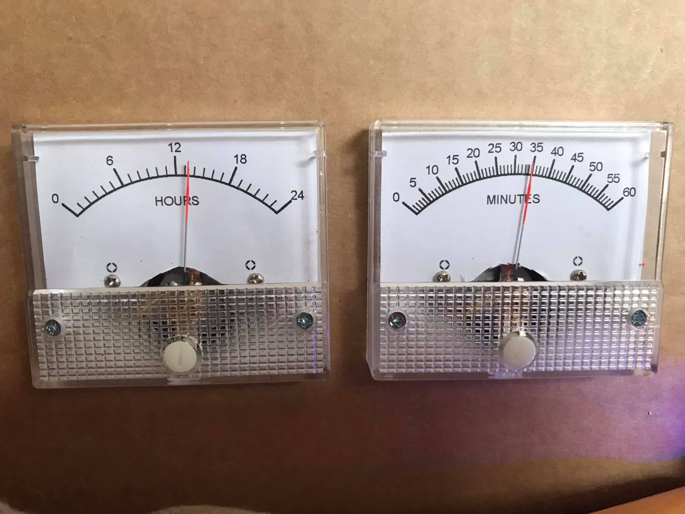
9.2.1 What they are
The photo shows two cheap plastic-bezel analog panel meters, side by side, already re-faced for clock use: the left meter is lettered 0–24 with “HOURS” under the arc, the right meter 0–60 with “MINUTES.” Both are the small rectangular import meters with a clear ribbed plastic bezel, two screw terminals, and a front zero-adjust screw — the same class of meter the abbtech build used, and exactly the “few-dollars-each, easy to re-face” starting point Vol 3 recommends. The red needles sit mid-arc (the hours needle near 12, the minutes needle near 35) — parked, not driven, in the photo. This is a two-meter design: hours and minutes only, with no seconds meter, and the hours meter uses a 0–24 scale (24-hour time) rather than the 0–12 of the three-meter build.
9.2.2 How a two-meter variant would be driven
The two-meter clock is the same principle with fewer channels — and is the gentler entry point for a first build. Everything in § 9.1’s drive analysis carries over:
- Two channels instead of three. Drop the seconds meter and you need only two PIC outputs, two 4.7 kΩ series resistors, and two meters. The PIC16F628A has the pins to spare; the firmware simplifies to an hours-and-minutes update with no seconds animation to smooth.
- A 0–24 hours scale. The HOURS meter reads 0–24, so the firmware maps a full day onto one full-scale swing: midnight = zero deflection, noon = half scale, the run-up to 24:00 = full scale. That is friendlier to read at a glance than a 0–12 face (no AM/PM ambiguity), at the cost of a more crowded dial.
- Same calibration discipline. Two cheap meters still have unit-to-unit spread, so the same per-meter full-scale trim is needed — whether by a scale-adjust mode like abbtech’s, or simply by tuning each series resistor until the needle hits full scale at the maximum count.
As a project, the two-meter “So Analog” is best understood as a stripped-down Multimeter Clock: lose a third of the parts and the seconds sweep, keep the entire engineering, and end up with a clock that is arguably more legible because two slow needles are easier to read at a distance than three. It is the recommended first build for anyone who finds the three-meter version daunting.
9.3 Honest notes and gotchas
The Multimeter Clock is a charming, well-documented design, but it has real limitations that an honest walk-through must name. None is a flaw exactly — each is a consequence of a deliberate simplicity — but knowing them up front saves disappointment.
- No battery-backed RTC — it loses time on every power-off. This is the single biggest limitation. There is no DS1302/DS3231-class real-time clock and no coin-cell backup in the BOM; timekeeping lives entirely in the PIC’s firmware, running off the 20 MHz crystal. Pull the plug and the time is gone — on the next power-up the PWM outputs default to ~50 % and you must set the time again by hand. (Contrast the misfiled TIX clock of § 9.4, which does carry a DS1302 + battery.) For a clock that is never unplugged this is a non-issue; for one on a switched outlet it is a daily chore, and the obvious first hack — with that 20 % free code space — is to add an I²C RTC.
- Modifying the firmware needs PICBasic Pro, and there isn’t much room. The source is PICBasic Pro; to change any behavior you need that (commercial) compiler. And while ~20 % of the 2 K code space is free, that is not a lot — adding an RTC driver, a 12/24-hour toggle, or a smoother seconds sweep will compete for those few hundred words of program memory. The pre-programmed PIC works out of the box; changing it is the gated step.
- The ≈25 mA-per-pin limit constrains meter choice. Each PIC output sources at most about 25 mA, and it drives the meter directly through a resistor with no buffer. That is luxurious for a 0.5 mA meter but it sets a hard ceiling: any meter whose full-scale current exceeds ~25 mA (or, practically, anything above a few mA once you account for the resistor drop) cannot be driven directly and needs a transistor stage (Vol 4). Stick to low-full-scale microammeter/milliammeter movements and the direct-drive design just works.
- Unit-to-unit meter spread makes per-meter calibration mandatory. These are inexpensive import meters; no two share the same exact full-scale current or internal resistance, and the author’s own meters were mismatched enough that their bezels weren’t even printed alike. The scale-adjust mode exists because you cannot skip this: an un-trimmed meter reads visibly wrong at the top of the dial. Calibrate all three (or two) to full scale before trusting the time — it is the one step of this build you cannot omit.
Taken together: the Multimeter Clock is an excellent first analog-needle clock — cheap, safe, fully documented, kit-backed — provided you accept that it must be re-set after a power loss and calibrated before first use.
9.4 File inventory of 02-inputs/Simpson/
What is actually on disk for this subproject, and one thing that does not belong:
Table 2 — What is actually on disk for this subproject, and one thing that does not belong
| File | What it is | Belongs here? |
|---|---|---|
Multimeter-Clock.pdf | The full abbtech Instructables article (intro, how-it-works, parts list, schematic on p. 5, the CNC-MDF housing build, and the usage/calibration procedure) — the primary source for this whole volume | Yes — the core collected project |
Multimeter Clock.url | A Windows internet shortcut to the project’s YouTube demo (youtube.com/watch?v=0gSPxQY-dOk) | Yes — the moving demo of the same clock |
So Analog.jpg | The owner’s two-meter build parts — re-faced 0–24 HOURS and 0–60 MINUTES panel meters (§ 9.2) | Yes — the owner’s own collected parts |
UTixClock.pdf | A TIX LED-grid clock build (Arduino Nano + DS1302 RTC + 74HC595 shift registers driving a matrix of LEDs) | No — misfiled. Not a meter-movement clock; belongs to the TIX subproject and should be relocated. |
The UTixClock.pdf misfile is worth flagging twice because it is easy to assume everything in a
folder belongs together. It is a count-the-lit-cells LED clock — a completely different display
technology, with a real RTC and a 74HC595 LED-driver chain — and it has no panel meter,
no moving coil, and nothing to do with this deep dive. It is excluded here (as Vol 1 § 1.7
also notes) and should move to TIX/02-inputs/.
References
- abbtech (Alan Parekh, Hacked Gadgets), Multimeter Clock, Instructables, 2010 —
02-inputs/Simpson/Multimeter-Clock.pdf; demo video02-inputs/Simpson/Multimeter Clock.url(https://www.youtube.com/watch?v=0gSPxQY-dOk). Three analog meters (H/M/S), PIC16F628A @ 20 MHz, meters on 0.5 mA DC driven through 4.7 kΩ resistors, PICBasic Pro firmware with a scale-adjust calibration mode that stores per-meter trims in EEPROM, custom MeterBasic dial faces, layered ½-inch MDF CNC case with v-carved Simpson 260 details. A “Multimeter Clock Kit” (controller + pre-programmed PIC) is sold via the article. - MeterBasic by Tonne Software — custom analog meter-face design program used for the Hours/Minutes/Seconds dials. Re-facing technique: Vol 8.
- Owner’s two-meter “So Analog” parts —
02-inputs/Simpson/So Analog.jpg(re-faced 0–24 HOURS and 0–60 MINUTES panel meters). - Cross-references: meter physics → Vol 2; meter selection/sourcing → Vol 3; PWM drive, the 25 mA limit, calibration → Vol 4; PIC16F628A timebase, 1/10 s interrupt, EEPROM trims → Vol 5; ordered build steps (inventory + walk-through) → Vol 6; buy-a-kit/finished options → Vol 7; MeterBasic faces + the MDF instrument enclosure → Vol 8. The misfiled
UTixClock.pdfbelongs to the TIX subproject.
Footnotes
-
abbtech (Alan Parekh, Hacked Gadgets), “Multimeter Clock,” Instructables, 15 August 2010 — Intro and Step 1 (“How it Works”): three multimeters showing hours/minutes/seconds; a 16F628A PIC keeps time and outputs a calculated current to each meter; an interrupt fires every 1/10 second to increment a tenth-second counter, and a routine advances the time by one second once a full second accumulates.
02-inputs/Simpson/Multimeter-Clock.pdf. Source: http://www.instructables.com/id/Multimeter-Clock/; author blog: http://hackedgadgets.com; personal site: http://alan-parekh.com. ↩ ↩2 -
The article’s parts list names the diode “1N4401.” That is not a standard part number (the 1N4001 is the common 1 A rectifier used for reverse-polarity protection; 2N4401 is an NPN transistor), so “1N4401” is almost certainly a transcription of 1N4001. The BOM table reproduces the article’s text verbatim; the functional role (supply reverse-polarity / I/O clamp) is inferred from placement. The published schematic (p. 5) is reproduced at small size, so the exact net of each of the five diodes is not asserted here — build to the schematic sheet itself. ↩ ↩2
-
abbtech, “Multimeter Clock,” Step 1: “The meters are all in 0.5 DCmA mode, the negative lead of each meter is grounded and the positive leads are connected to a microcontroller output via a current limiting resistor. The resistor in this case is a 4.7K however this can be adjusted depending on the meter current scale available. Keep in mind that the PIC can deliver a maximum of 25mA to each meter so a meter with a lowest setting above 25mA would not work without additional circuitry.” Firmware language, code-space, PWM default, LED behavior, MeterBasic faces, the CNC/MDF housing, and the scale-adjust + time-set procedures are from Steps 2–5 of the same article. ↩
Comments (0)