Meter Movement · Volume 2
How a Moving-Coil Meter Works
The d'Arsonval movement, why its scale is linear, full-scale current and internal resistance, and the damping that turns a twitchy needle into a smooth sweep
A meter-movement clock has no display physics to speak of — no glow, no filament, no phosphor. Its “display” is a moving-coil meter, an electromechanical instrument that converts a current into a needle angle and has done so, essentially unchanged, since the 1880s. To drive one well — to make a needle settle at exactly twelve o’clock and sweep the seconds without jitter — you have to understand the small machine under the dial: a coil in a magnetic field, a hairspring pulling back, and a damping mechanism that decides whether the needle glides to its mark or bounces around it. This volume is that machine. Three facts carry through the whole series and are worth stating before the algebra: a moving-coil meter is fundamentally a current meter; its scale is linear because two torques balance; and its needle is deliberately slow, which is both the clock’s charm and the thing that quietly smooths the driver’s PWM into a clean level (Vol 4).
2.1 The d’Arsonval movement — what is inside
The moving-coil meter is the d’Arsonval movement, named for Jacques-Arsène d’Arsonval (with Marcel Deprez), who in the 1880s fixed a current-carrying coil on pivots in the field of a permanent magnet so that it would turn through a repeatable angle.1 Edward Weston’s portable Weston meter (1888) added the rugged, temperature-compensated construction that every panel meter — and the Simpson 260 the worked build imitates — still copies (Vol 1, §1.2). Strip the bezel and dial off any analog panel meter and the same parts are inside.
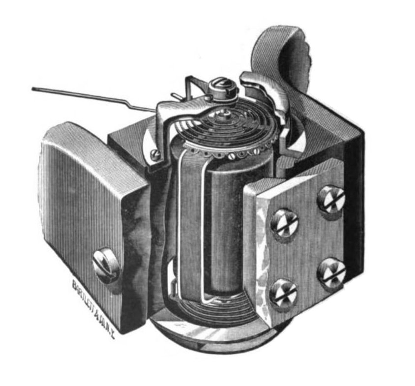
2.1.1 The parts and what each does
- Permanent magnet and soft-iron core. A horseshoe or ring magnet establishes a magnetic field; a cylindrical soft-iron core sits inside the coil. The core’s job is geometric: it shapes the gap so the field is radial everywhere the coil sits — the flux always crosses the coil sides at right angles, at the same density, regardless of the coil’s angle. This radial-field trick is exactly why the scale comes out linear (§2.2). Modern movements often use a core-magnet (the magnet is the core, with a soft-iron return ring outside) for a more compact, better-shielded package; the physics is identical.
- Coil wound on a former. Many turns of fine enamelled copper wire are wound on a light rectangular former (bobbin), usually thin aluminium. The former does double duty: it holds the winding rigid, and — being a closed conducting loop — it provides eddy-current damping (§2.5). The coil pivots in the radial gap.
- Pivots — pivot-and-jewel or taut-band. The coil-and-pointer assembly must turn with almost no friction. The classic suspension is pivot-and-jewel: hardened steel pivot points run in polished sapphire or glass V-jewels, like a watch bearing. The modern alternative is taut-band: the coil hangs on two thin metal ribbons under tension, with no pivots and no jewels at all — the ribbons both support the coil and supply the restoring torque by twisting. Taut-band has zero pivot friction, so it has no “stiction” dead-band and better low-end resolution; pivot-and-jewel is cheaper and more tolerant of shock (§2.6).
- Hairsprings. Two flat spiral hairsprings (phosphor-bronze or a special alloy), wound in opposite senses, do two jobs at once: they provide the restoring torque that opposes deflection, and they carry the current in and out of the coil (the coil has no other electrical connection). Opposite winding cancels their thermal expansion so zero does not drift with temperature. In a taut-band movement the bands replace the hairsprings for both jobs.
- Pointer, balance, and zero-adjust. A light pointer (often a knife-edge blade over a mirror scale, to kill parallax) is fixed to the coil; tiny balance weights on cross-arms make the assembly balance about its pivot so the reading does not depend on whether the meter sits flat or upright. A zero-adjust screw rotates the outer end of one hairspring to set the rest position exactly on the zero (or, for a clock, the chosen start of scale).

2.2 The torque balance and why the scale is linear
The single most useful fact about a moving-coil meter is that its needle angle is directly proportional to the current — double the current, double the deflection. That linearity is not a happy accident; it falls straight out of balancing two torques, and the radial field (§2.1.1) is what makes the algebra clean.
2.2.1 The drive (deflecting) torque
When current I flows through the coil, each of the two coil sides (length ℓ, sitting in
flux density B, carrying current through N turns) feels a force F = N·B·I·ℓ. The two
sides are pushed in opposite directions across the gap, separated by the coil width w, so
together they make a couple — a torque:
τ_drive = N · B · I · ℓ · w = N · B · I · Awhere A = ℓ·w is the area enclosed by one coil turn. Because the field is radial, B
and the moment arm stay constant through the whole sweep, so τ_drive depends only on I —
not on the angle. With N = 100 turns, B = 0.20 T, A = 2.0 cm² = 2.0 × 10⁻⁴ m², and a
full-scale current I = 0.5 mA = 5.0 × 10⁻⁴ A (the worked build’s range):
τ_drive = 100 × 0.20 T × (5.0 × 10⁻⁴ A) × (2.0 × 10⁻⁴ m²)
        = 2.0 × 10⁻⁶ N·m  =  2.0 µN·m
A couple of micronewton-metres — a tiny torque, which is why the moving parts must be feather-light and the bearings nearly frictionless.
2.2.2 The restoring torque and the balance
The hairsprings (or taut bands) push back with a torque proportional to how far the coil has turned — an ordinary linear spring, in rotation:
τ_spring = k · θwhere k is the spring’s torsional stiffness (units N·m/rad) and θ is the deflection
angle. The needle stops where the two torques balance:
N · B · I · A = k · θ ⟹ θ = (N · B · A / k) · IEverything in the bracket is a fixed property of the meter, so θ ∝ I: the scale is
linear. Continuing the example, if full scale is θ_fs = 90° = π/2 = 1.571 rad, the
spring stiffness must be
k = τ_drive / θ_fs = (2.0 × 10⁻⁶ N·m) / (1.571 rad) = 1.27 × 10⁻⁶ N·m/radand the meter’s sensitivity is θ/I = (N·B·A)/k = 1.571 rad / 5.0 × 10⁻⁴ A ≈ 3.14 × 10³ rad/A, i.e. about 90° of sweep for half a milliamp. That single constant — degrees of needle
per milliamp — is the number the driver and the dial design must respect (Vols 3–4).

The headline, carried into every later volume: a moving-coil meter is a current meter with a linear scale. Whatever a meter’s dial says — volts, milliamps, “HOURS” — the needle is reporting the current through its coil, and that current maps to angle by the one straight line of Figure 2.2.
2.3 Full-scale current and internal resistance
Two numbers describe a movement well enough to drive it: the current that pins the needle at the top of the scale, and the resistance the driver sees looking into the terminals.
2.3.1 Full-scale current (I_fs)
The full-scale deflection current, I_fs, is the coil current that swings the needle to
the end of its travel. It is set by N, B, A, and k (§2.2) and is the meter’s defining
spec. Common bare movements come in a handful of values:
Table 1 — spec. Common bare movements come in a handful of values
| I_fs | Sensitivity (1/I_fs) | Typical use |
|---|---|---|
| 50 µA | 20 kΩ/V | sensitive VOM movements (Simpson 260 is 20 kΩ/V) |
| 100 µA | 10 kΩ/V | general panel meters |
| 0.5 mA | 2 kΩ/V | the worked build’s range |
| 1 mA | 1 kΩ/V | rugged, easy-to-drive panel meters |
Lower I_fs means a more sensitive meter (a larger “ohms-per-volt” when made into a
voltmeter, §2.4) but a more delicate coil of finer wire. For clock work the choice is mostly
about what the driver can reach: a 0.5 mA movement is trivially driven from a PIC pin through
a resistor, whereas a 30 mA movement would want a transistor buffer (Vol 4). The one hard
rule is never exceed I_fs — past full scale the needle slams its stop and the fine coil
wire overheats (Vol 1, §1.10).
2.3.2 Internal resistance (R_m)
The internal (movement) resistance R_m is the DC resistance the terminals present — the
resistance of the fine coil wire plus the two hairsprings carrying the current. It ranges from
a few ohms on a low-sensitivity milliammeter to a few kilohms on a 50 µA microammeter (more
turns of finer wire). R_m matters three ways: it sets the voltage burden V_m = I_fs · R_m the meter drops at full scale (for a 0.5 mA / 100 Ω movement, V_m = 5.0 × 10⁻⁴ A × 100 Ω = 50 mV); it is a term in the multiplier and shunt formulas (§2.4); and — through the closed
former and the external circuit — it helps set the damping (§2.5). A movement is therefore
specified by the pair (I_fs, R_m), e.g. “0.5 mA, 100 Ω.”
2.4 Voltmeter versus ammeter — the same movement underneath
A surplus drawer holds meters labelled “VOLTS,” “mA,” and “AMPERES,” but they are the same
d’Arsonval current meter with a resistor added. Knowing this is what lets you re-purpose
any panel meter for a clock: you read the bare movement’s (I_fs, R_m) and ignore the
printed units (Vol 3).
2.4.1 A voltmeter is a movement plus a series multiplier
To read voltage, put a large series multiplier resistor R_s in front of the movement.
The two in series draw I_fs when the wanted full-scale voltage V_fs is applied:
V_fs = I_fs · (R_s + R_m) ⟹ R_s = V_fs / I_fs − R_mFor a 0.5 mA / 100 Ω movement read as a 10 V full-scale voltmeter:
R_s = 10 V / (5.0 × 10⁻⁴ A) − 100 Ω = 20 000 Ω − 100 Ω = 19 900 ΩThe meter’s input resistance is then R_s + R_m = 20 kΩ, i.e. 1/I_fs = 1/(0.5 mA) = 2 kΩ/V times the 10 V range — the “ohms-per-volt” sensitivity figure on the dial. (A 50 µA
movement gives 20 kΩ/V; hence the Simpson 260’s famous 20 kΩ/V spec, Vol 1.)
2.4.2 An ammeter is a movement plus a parallel shunt
To read a current larger than I_fs, put a small parallel shunt resistor R_sh across
the movement so the shunt carries the excess. At full scale the movement still takes I_fs,
the shunt takes I_full − I_fs, and both have the same voltage across them:
I_fs · R_m = (I_full − I_fs) · R_sh ⟹ R_sh = R_m · I_fs / (I_full − I_fs)For the same 0.5 mA / 100 Ω movement made into a 1 A ammeter:
R_sh = 100 Ω × (5.0 × 10⁻⁴ A) / (1 A − 5.0 × 10⁻⁴ A) = 0.0500 Ω / 0.9995 ≈ 0.0500 ΩA 50 milliohm strap — which is why ammeter shunts look like bus-bars, not resistors. The lesson for the clock: under the dial there is always a current meter. A meter-movement clock drives that current meter directly with a small coil current, so you generally want the bare microammeter / milliammeter movement (or a voltmeter you stay within), not a high-range ammeter whose tiny shunt swamps the movement (Vol 3).
2.5 Damping — the part that matters for a sweeping clock needle
So far the analysis was static — where the needle finally rests. But a clock’s needle is always moving: the seconds meter especially is never still, and even the minutes needle steps every minute (or creeps, with a continuous driver). What the needle does on the way to its new reading — glide smoothly, or overshoot and ring around it — is set by damping, and it is the single mechanical property that most affects how a meter clock looks.
2.5.1 Why an undamped meter rings
The coil-and-pointer assembly has rotational inertia J and is restrained by spring
stiffness k. By itself that is an oscillator: nudge it and it swings about the rest point
at its natural frequency ω_n = √(k/J), in principle forever. Step the current up and an
undamped needle would shoot past the new reading, swing back past it, and oscillate around
the true value for a long time — useless for reading, and visually awful on a clock. Damping
adds a torque proportional to angular velocity, τ_damp = D · θ̇, that bleeds the energy
away. The equation of motion becomes a standard second-order system:
J · θ̈ + D · θ̇ + k · θ = τ_drive(t)2.5.2 Air-vane and eddy-current damping
Meters supply that velocity-proportional torque two ways:
- Air-vane (pneumatic) damping — a light vane attached to the coil sweeps a sealed air chamber; the air resists fast motion. Common in larger switchboard meters; entirely mechanical, independent of the circuit.
- Eddy-current (electromagnetic) damping — the usual method in panel meters, and a free by-product of the construction. The aluminium former the coil is wound on is a closed conducting loop moving in the magnet’s field; its motion induces eddy currents, and those currents drag against the field (Lenz’s law) with a torque opposing the motion. Crucially, the coil winding itself also forms a loop through the external circuit, so part of the electromagnetic damping depends on the resistance the driver presents: a low external resistance lets larger braking currents flow and damps more; an open circuit removes that path and damps less. This is why meter makers quote a critical damping resistance external (CDRX) — the external resistance that yields near-critical damping — and why the driver’s output resistance is quietly part of the clock’s mechanical behaviour (Vol 4).
2.5.3 Under-, critically, and over-damped response
The behaviour is captured by the damping ratio ζ = D / (2√(k·J)):
- Under-damped (
ζ < 1) — the needle overshoots and rings, settling slowly. A bare movement on a high-impedance drive can land here, and the seconds needle would visibly bounce. - Critically damped (
ζ = 1) — the fastest approach with no overshoot. The ideal. - Over-damped (
ζ > 1) — no overshoot but sluggish, the needle crawling to its mark.
Real meters are deliberately tuned slightly under critical (typically ζ ≈ 0.6–0.8),
which trades a tiny, fast overshoot for a noticeably quicker response — a good bargain for a
panel instrument and a clock alike.

2.5.4 Settling time and ballistic response
Two timing numbers follow. The settling time — how long until the needle stays within,
say, ±2 % of the new reading — is roughly t_s ≈ 4 / (ζ · ω_n) for a near-critically-damped
movement, typically a few hundred milliseconds to a second or two for a panel meter. That is
slow electrically, and it is the friend of the driver: the movement is a mechanical
low-pass filter, so a PWM drive averages out and the needle shows the smooth mean rather than
the switching ripple (Vol 4). The flip side is ballistic response — a kick shorter than
the movement’s response time deflects the needle in proportion to the charge (the
current-time integral) rather than tracking the instantaneous current. A clock should avoid
the ballistic regime: feed each meter a steady level (or a PWM whose period is far shorter
than t_s) so the needle reports a true average, not an impulse. The seconds needle’s constant
motion is exactly why its damping wants to sit near critical — enough to kill overshoot, not
so much that it lags the second it is meant to show.
2.6 Temperature, and taut-band versus pivot-and-jewel
Two second-order effects round out the picture; both matter when you ask three needles to read true across a whole dial (Vol 4’s calibration).
Temperature. Three things drift with temperature: the copper coil’s resistance (R_m
rises with heat, the largest effect when the meter is fed from a voltage), the magnet’s flux
density B (falls slightly), and the hairspring stiffness k. Quality movements fight this
with the counter-wound hairspring pair (cancelling spring drift and thermal zero shift) and,
in precise voltmeters, a series swamping resistor of low-temperature-coefficient material
that makes the copper’s drift a small fraction of the total. For a low-voltage clock at room
temperature the drift is small, but it is real, and it is one reason a single full-scale trim
per meter (Vol 4) is worth keeping accessible.
Taut-band versus pivot-and-jewel. The suspension choice (§2.1.1) trades friction against ruggedness:
- Pivot-and-jewel — pivots in jewel bearings. Cheaper, shock-tolerant, but has real bearing friction, which shows up as a small dead-band and as hysteresis (the needle rests a hair short of the true value, differently coming up versus down). Tapping the glass — the old laboratory habit — jars the needle past the friction to its true reading.
- Taut-band — coil slung on tensioned ribbons, no pivots, no jewels, no friction. No dead-band, finer resolution, better repeatability, and immune to pivot wear; more delicate to severe shock. For a clock that wants the needle to land on the same mark every minute, the frictionless taut-band movement is the nicer behaviour, though either works.
2.7 What carries forward
The next volumes assume three results from this one. One: a moving-coil meter is a linear
current meter — θ = (N·B·A/k)·I — so to place the needle you control the coil current,
and a “voltmeter” or “ammeter” label just means a resistor was added (§2.2, §2.4). Two: a
movement is specified by (I_fs, R_m); pick meters whose I_fs your driver can reach and
whose R_m you can account for (Vols 3–4). Three: the needle is a damped second-order
system that is deliberately slow — which is why the seconds needle sweeps instead of
snapping, why PWM drive works at all, and why getting the damping near critical (partly through
the driver’s output resistance) is what separates a smooth clock from a twitchy one (§2.5,
Vol 4). With the movement understood, Vol 3 turns to choosing and sourcing real meters.
2.8 References (Vol 2)
- Moving-coil (d’Arsonval / PMMC) instrument theory — radial-field construction,
τ = N·B·I·Abalanced byτ = k·θgiving a linear scale; full-scale currentI_fs, internal resistanceR_m, the series-multiplier voltmeter (R_s = V_fs/I_fs − R_m) and parallel-shunt ammeter (R_sh = R_m·I_fs/(I_full − I_fs)); and the second-order damped step response with critical-damping-resistance-external (CDRX). Standard instrumentation-engineering material (e.g. Golding & Widdis, Electrical Measurements and Measuring Instruments; Sawhney, A Course in Electrical and Electronic Measurements and Instrumentation). - Worked-build anchor: Multimeter Clock by abbtech (Alan Parekh, Hacked Gadgets), 2010 — three moving-coil panel meters on their 0.5 mA DC range, driven from a PIC16F628A through 4.7 kΩ resistors. Held in
02-inputs/Simpson/. See Vol 1 and the worked build in Vol 6.
Footnotes
-
The d’Arsonval (moving-coil) galvanometer is named for Jacques-Arsène d’Arsonval, with Marcel Deprez, in the 1880s; Edward Weston’s portable Weston meter (1888) added the temperature-compensated coil, taut hairsprings, and rugged pivoted-coil construction that all later panel meters inherit. See Vol 1, §1.2 and its reference 1. ↩ ↩2
Comments (0)