Meter Movement · Volume 1
Overview & Decision Tree
What a meter-movement clock is, the ways to build or buy one, and which path fits your bench
A meter-movement clock tells the time with the swing of an analog panel-meter needle. There is no display to light and no digit to decode: an ordinary moving-coil voltmeter or milliammeter — the kind with a white dial, a thin pointer, and a clear plastic bezel — is re-faced so that its scale reads hours, minutes, and seconds instead of volts or milliamps, and a small circuit feeds each meter exactly the current that points its needle at the right number. Three meters side by side, marked HOURS, MINUTES, and SECONDS, become a clock whose charm is the slow, smooth sweep of three pointers and the honest vintage look of laboratory instruments. The engineering interest is not in any display physics but in the meter itself — a hundred-and-forty-year-old electromechanical movement — and in the small art of driving it precisely, damping it, and calibrating its full scale.
Note — this is the meter-movement technology overview. Specific meter-movement clocks Jeff owns or builds — their design, construction, and operation — are documented as their own deep dives in this technology’s
clocks/folder, one folder per clock, each avol*.mdseries with a Design → Building → Running spine. This volume series covers the technology in general; the per-clock dives go deep on individual units.
This ten-volume reference covers the meter-movement clock at depth: the d’Arsonval moving-coil physics that turns a current into a needle angle, how to pick and source the right meters, the drive electronics that map time onto deflection (PWM and a filter, a current-limiting resistor, or a proper voltage-to-current source), the timebase and counting logic, a complete worked build from a published design held in this hub, the buy-a-kit options, the craft of custom dial faces and the instrument-panel enclosure, and a laminate-ready cheatsheet. It is written for an experienced maker with an electronics bench and — for the enclosure — access to a CNC or laser, but the electronics are gentle: the whole clock lives at a safe 9–12 V, and the hardest part is a soldering iron and a steady calibration.
1.1 What a meter-movement clock actually is
Strip away the vintage dials and a meter-movement clock is the same four subsystems every clock in this hub has, with the display replaced by an electromechanical indicator — and, unlike the stepper-driven gauge clock next door in the Mechanical hub, the indicator moves by genuine electrical deflection, not by a motor stepping to a position:
- The meters themselves — two or three (occasionally one) moving-coil panel meters. Each is a d’Arsonval movement: a small coil pivoted in the field of a permanent magnet, restrained by a hairspring, so the needle deflects through an angle proportional to the current through the coil (Vol 2). A meter reads full scale at a defined full-scale current — the worked build uses meters on their 0.5 mA range — and the dial is re-lettered 0–12 (or 0–24) and 0–60 so that “full scale” means “twelve o’clock” or “sixty minutes.”
- The driver — something must turn a desired time into the right coil current. Because deflection tracks current (or, through the meter’s internal resistance, voltage), a microcontroller produces a per-meter analog level — most simply a PWM output through a current-limiting resistor, smoothed by the meter’s own slow mechanical response — and the needle settles where that current puts it (Vol 4). The worked build drives each meter from a PIC output pin through a 4.7 kΩ resistor.
- A timebase and counting logic — a microcontroller keeps time from a crystal and computes, every fraction of a second, what deflection each meter should show. The worked build uses a Microchip PIC16F628A with a 20 MHz crystal and a tenth-of-a-second interrupt (Vol 5).
- The structure that ties them together — a 5 V regulator, three time-set buttons, a calibration (“scale-adjust”) mode that stores each meter’s full-scale trim in non-volatile memory, and an enclosure that frames the meters as an instrument panel.

The thing that makes a meter-movement clock a project rather than a purchase is not difficulty in any one subsystem — none is hard — but the calibration and the craft: a meter is an analog device with a real full-scale current, a non-zero internal resistance, a mechanical damping characteristic, and unit-to-unit spread, so making three needles read true across the whole dial takes a trim per meter and a well-drawn custom face. The engineering is friendly; getting the pointers to tell the truth is the work.
1.2 A one-paragraph history
The moving-coil meter is older than almost everything else in this hub. The galvanometer became a practical pointer instrument when Jacques-Arsène d’Arsonval and Marcel Deprez fixed the coil on pivots between the poles of a permanent magnet in the 1880s — the “d’Arsonval movement” still named after him — and Edward Weston turned it into the rugged, portable Weston meter of 1888, adding the temperature-compensated coil, the taut hairsprings, and the knife-edge pointer that every panel meter still copies.1 For a century the moving-coil meter was how you read an electrical quantity, and the Simpson 260 volt-ohm-milliammeter (introduced 1936) became the archetypal analog multimeter — the instrument the worked build deliberately imitates, down to a CNC-engraved Simpson-260 face. Digital meters and displays overtook the moving-coil meter from the 1970s, but the movement never disappeared: cheap new panel meters are still made, surplus Simpson and Weston instruments are plentiful, and the smooth analog sweep — so unlike a digital clock’s jump — has made the panel-meter clock a favorite maker project. It is, in a sense, the same impulse as the nixie clock: take a beautiful obsolete way of showing a number and make it tell the time.
1.3 The ways to get a meter-movement clock
The spectrum runs from buying a finished novelty clock to designing your own driver, and the center of gravity is build it yourself — the parts are cheap and ubiquitous. This hub recognizes four first-class paths, and the series is organized so that whichever one you choose, a volume goes deep on it.
Table 1 — 1.3 The ways to get a meter-movement clock
| # | Path | Effort | Cost | Covered in |
|---|---|---|---|---|
| 1 | Buy a finished meter clock (Etsy / Tindie novelty “voltmeter clocks”) | none | $$ | Vol 7 |
| 2 | Buy a kit and solder it (the Multimeter Clock Kit, or a generic voltmeter-clock PCB) | medium | $ | Vol 7 |
| 3 | Build the collected design — the Multimeter Clock from the files in this hub | high | $ | Vol 6 |
| 4 | Design from scratch — your own driver and firmware around meters you source | very high | $ | Vols 3–5 |
Path 3 is the worked example throughout the engineering volumes: the hub holds the complete Multimeter Clock by abbtech (Alan Parekh, Hacked Gadgets) — a three-meter hours/minutes/seconds clock driven by a PIC16F628A, with the construction article, the parts list, the schematic, the custom meter faces, and the CNC enclosure approach all documented (Vol 6, with the project walk-through in Vol 9).
1.4 Decision tree — which path is right for this build
Work top-down; stop at the first “yes.”
- Do you want a finished analog clock on the shelf with no soldering? → Path 1. Search “voltmeter clock” or “panel meter clock”; Vol 7 covers the genre and what to look for.
- Do you enjoy soldering and want a guaranteed-working circuit? → Path 2, a kit. The Multimeter Clock Kit (the controller for the collected design) is the obvious one; Vol 7 covers it and the generic single-board voltmeter clocks.
- Do you want the best-documented meter clock there is, with article, schematic, custom faces, and case files in hand, and you’re happy on perfboard? → Path 3, the collected Multimeter Clock. Vol 6 is the worked build; Vols 2–5 are the engineering reference behind it.
- Do you want to design your own — different meters, a different MCU, a voltage-to-current driver, a continuously sweeping seconds meter? → Path 4. Vols 2–4 are the meter and driver engineering you will live in, and Vol 3 helps you choose meters that your driver can actually reach full scale.
Whatever the path, Vol 4’s calibration section and Vol 8’s dial-face craft are what make or break the result — an uncalibrated meter clock reads visibly wrong at the top of the scale, and a poorly drawn face spoils the one thing this clock is for: looking like a real instrument.
1.5 The meters — a first orientation
You cannot choose a build without choosing meters, so here is the orientation the rest of the series builds on. Meters are sorted by what they measure, by full-scale current, and by construction, and for clock work the field narrows quickly (Vol 3 is the full treatment):
- Full-scale current is everything. A meter deflects full scale at a specific current — common panel meters are 50 µA, 100 µA, 0.5 mA, or 1 mA at full scale. The driver has to reach that current: the worked build’s PIC pin can source about 25 mA, so a 0.5 mA meter is trivially driven through a resistor, while a 30 mA meter would need a transistor buffer. Lower full-scale current is friendlier.
- A voltmeter is just a milliammeter with a resistor. Every moving-coil “voltmeter” is a current meter with a series multiplier resistor inside; an “ammeter” is one with a parallel shunt. For a clock you usually want the bare microammeter/milliammeter movement, or a voltmeter you drive within its range (Vol 2–3).
- Cheap new panel meters vs. a vintage instrument. A handful of new plastic-bezel panel meters (like the two re-faced 0–24 h and 0–60 min meters collected in this hub) cost a few dollars each and are easy to re-face; a genuine Simpson 260 or Weston is the real-instrument look but is larger, pricier, and worth preserving. Vol 3 covers the trade-off and sourcing.
All of these are moving-coil devices: a current through a pivoted coil makes a torque against a hairspring, and the needle settles at the angle where the two balance. The one consequence to carry forward is that deflection is analog, continuous, and a little sluggish — the needle does not snap, it sweeps, and that mechanical lag is both the clock’s signature charm and the thing that quietly filters the driver’s PWM into a smooth level (Vols 2 and 4).
1.6 Meter-movement vs. the stepper gauge clock (the one clarification)
There is one boundary worth stating up front, because this hub contains both kinds of needle clock and they are often confused. The Aviation gauge clock in the Mechanical deep dive also sweeps needles across instrument-style dials — but it does so with stepper motors and gear reduction, positioning each needle to a commanded angle. A meter-movement clock has no motor: the needle is the meter’s own moving coil, and it deflects because a current flows through it, exactly as it would if you connected the meter to a battery. The distinction is not pedantic — it changes the whole engineering. A stepper clock worries about microsteps, homing, and gear backlash (Mechanical Vols 3–4); a meter clock worries about full-scale current, internal resistance, damping, and linearity (this series’ Vols 2–4). When a project drives a needle by PWM-into-a-coil, it is a meter-movement clock and belongs here; when it drives a needle by step-and-direction into a motor, it is the Mechanical hub’s gauge clock.2
1.7 What the owner already has collected
One published project anchors the series, plus a small two-meter build’s parts:
- “Multimeter Clock” by abbtech (Alan Parekh, Hacked Gadgets, 2010). A three-meter clock — hours, minutes, seconds — built around a PIC16F628A at 20 MHz. Each meter runs on its 0.5 mA DC range, negative lead grounded, positive lead driven from a PIC output through a 4.7 kΩ current-limiting resistor; the firmware (PICBasic Pro) keeps time from a tenth-of-a-second interrupt and has a scale-adjust calibration mode that trims each meter to exactly full scale and stores the result in non-volatile memory. The custom HOURS / MINUTES / SECONDS meter faces were drawn in MeterBasic (Tonne Software), and the enclosure is layered ½-inch MDF, CNC v-carved with Simpson 260 details. The hub holds the construction article, the parts list, the schematic, the dial faces, and the build photos. This is the worked build of Vol 6 and the subject of the walk-through in Vol 8/9.
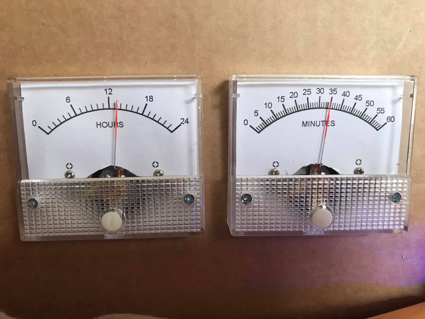
- A two-meter “So Analog” build’s parts — two plastic-bezel panel meters already re-faced
0–24 HOURS and 0–60 MINUTES (in
02-inputs/Simpson/), the kind of cheap-meter starting point Vol 3 recommends. Walked through alongside the worked build in Vol 9.
Note on a misfiled reference: a
UTixClock.pdfalso sits in this subproject’s inputs, but it is not a meter-movement clock — it is a TIX LED-grid clock (Arduino Nano + DS1302 RTC + 74HC595 shift registers driving a matrix of LEDs). It belongs to the TIX subproject and is excluded from this deep dive; it should be relocated.
1.8 How this series is organized
The series moves from principle to practice to project to polish:
- Principle (Vols 2–5) — how a moving-coil meter works, how to choose and source meters, how to drive them from a microcontroller, and the timebase/counting logic. Read these to understand any meter-movement clock.
- Project (Vols 6, 9) — the worked three-meter build start to finish, and a full walk-through of the collected design plus the two-meter parts.
- Buy & polish (Vols 7, 8, 10) — the buy-a-kit and finished options; the custom dial faces and instrument-panel enclosure; and the laminate-ready cheatsheet and glossary.
1.8.1 Volume-by-volume index
Table 2 — 1.8.1 Volume-by-volume index
| Vol | Title | Read it for |
|---|---|---|
| 1 | Overview & Decision Tree | (this volume) — the map and the path choice |
| 2 | How a Moving-Coil Meter Works | d’Arsonval physics, torque vs current, hairspring, damping, ballistic response, taut-band vs pivot |
| 3 | Meters for a Clock — Selection & Sourcing | full-scale current, internal resistance, voltmeter vs ammeter, Simpson 260 vs cheap panel meters, where to buy |
| 4 | Driving the Meter | current vs voltage drive, PWM + filtering, resistor sizing, the 25 mA limit, V-to-I sources, linearization, calibration |
| 5 | Timebase & Counting Logic | the PIC16F628A, 20 MHz crystal, the 1/10 s interrupt, mapping time to deflection, smoothing the seconds, EEPROM trims |
| 6 | Build It Yourself | the collected Multimeter Clock: parts → perfboard → schematic → PIC flashing → scale calibration → MDF/CNC case |
| 7 | Buy a Kit or Finished Clock | the Multimeter Clock Kit, voltmeter-clock genre, sourcing meters, pricing, trade-offs |
| 8 | Dials, Faces & Enclosure | MeterBasic face design, re-facing a meter, the instrument aesthetic, the Steampunk cross-link |
| 9 | The Collected Project | a full walk-through of abbtech’s design and the two-meter parts — circuit, firmware, calibration, case |
| 10 | Cheatsheet & Glossary | meter equations, PWM→V and RC-filter math, BOM quick-ref, PIC pinout, source URLs, A–Z terms |
1.9 What this series is — and is not
It is a build-and-understand reference for clocks that show time on analog moving-coil panel meters, grounded in a complete published design held in this hub and in the physics of the d’Arsonval movement.
It is not a guide to building or repairing the meters themselves — it tells you how to choose, drive, re-face, and calibrate a panel meter, but a damaged movement (a bent pointer, a broken hairspring, a rubbing coil) is a job for a meter-repair reference, not this one. Nor is it the stepper gauge clock (that is the Mechanical hub’s Aviation build — §1.6), the TIX LED-grid clock (its own subproject — §1.7), or a horology text. Where the mechanism or aesthetic overlaps another hub deep dive, this series cross-links to it.
1.10 Safety, stated once up front
This is the easy part. A meter-movement clock runs from a 9–12 V DC wall supply into a 5 V regulator; there is no high voltage anywhere, no charged high-voltage capacitor, nothing that can bite you. The cautions in this series are therefore mostly about the meters’ delicacy, not your safety: a moving-coil movement is fragile — drive it past full scale and you can slam the needle against its stop or overheat the fine coil wire, and a bent pointer or a broken hairspring is hard to fix. The disciplines that matter — never exceed a meter’s full-scale current, ramp gently on power-up, and calibrate before trusting the dial — are in Vols 4 and 6. The only conventional hazards are the ordinary ones of the enclosure work (a CNC router or laser cutter, MDF dust, spray paint), covered in Vol 6. There are no high-voltage warnings here because there is no high voltage.
1.11 Photo policy
Photographs in this series come from three sources, credited in every caption: any of the owner’s own build photos (including the two-meter parts in this hub); license-clean images from Wikimedia Commons / Openverse fetched through the project’s Photo Helper (with the full attribution line reproduced verbatim); and, for diagrams, hand-authored SVG in the paper-background house style. Where a figure is still to be sourced it appears as a FIGURE SLOT placeholder describing what should go there. No images are scraped from arbitrary copyrighted web pages.
1.12 References (Vol 1)
- Multimeter Clock by abbtech (Alan Parekh, Hacked Gadgets), Instructables, 2010 — three analog meters (H/M/S), PIC16F628A at 20 MHz, meters on 0.5 mA DC driven through 4.7 kΩ resistors, PICBasic Pro firmware with a scale-adjust calibration mode, custom MeterBasic dial faces, layered ½-inch MDF CNC case with v-carved Simpson 260 details. Construction article, parts list, schematic, faces, and build photos held in
02-inputs/Simpson/. Source: http://www.instructables.com/id/Multimeter-Clock/; author blog: http://hackedgadgets.com. - Two-meter “So Analog” parts (0–24 HOURS, 0–60 MINUTES re-faced panel meters) held in
02-inputs/Simpson/. _shared/comparison.md(cross-technology decision matrix) and_shared/deep_dive_protocol.md.
Footnotes
-
The d’Arsonval (moving-coil) galvanometer is named for Jacques-Arsène d’Arsonval (with Marcel Deprez), 1880s; Edward Weston’s portable Weston meter (1888) added temperature compensation and the rugged pivoted-coil/hairspring construction that all later panel meters and the Simpson 260 VOM (1936) inherit. The collected build engraves a Simpson 260 face into its enclosure. ↩
-
The Mechanical hub’s Aviation gauge clock (Mechanical deep dive, Vols 1, 4, 9) drives its needles with NEMA-17 stepper motors through TMC2208 microstepping drivers and gear reduction — point-to-point positioning, not coil deflection. The two needle-clock families are distinguished by their actuator: a moving coil (here) vs a stepper motor (there). ↩
Comments (0)