Meter Movement · Volume 3
Meters for a Clock — Selection & Sourcing
Choosing and buying the panel meters: full-scale current first, then internal resistance, sweep angle, matching, style, and where to find them
Volume 2 explained why a needle deflects: a current through a pivoted coil makes a torque against a hairspring, and the pointer settles at the angle where the two balance. This volume is the practical sequel — the choose-and-buy decision. You have understood the d’Arsonval movement; now you have to walk into a parts search, sort through a hundred near-identical panel meters, and come out with two or three you can actually drive to full scale, re-face cleanly, and trust across the whole dial. The order of the decisions matters, because the first one — full-scale current — quietly fixes how hard the rest of the build is. Get it right and the driver is one resistor per meter (Vol 4); get it wrong and you have signed up for a transistor buffer and a bench afternoon you did not need.
The collected Multimeter Clock by abbtech (Vol 1, Vol 6, Vol 9) made every one of these choices deliberately: three meters, all run on their 0.5 mA DC range, each driven from a PIC16F628A output pin through a single 4.7 kΩ resistor, with a per-meter scale-adjust calibration mode to absorb the unit-to-unit spread. The owner’s two-meter “So Analog” build made the cheaper version of the same call — two plastic-bezel panel meters re-faced 0–24 HOURS and 0–60 MINUTES. Both are worked examples of the rules below.
3.1 Full-scale current is the first decision
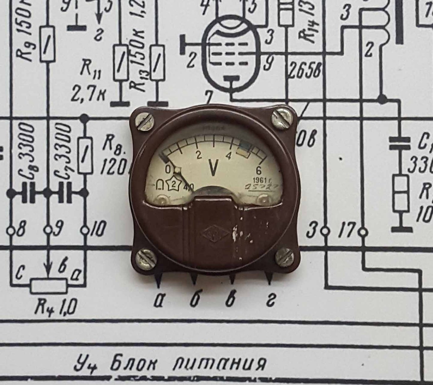
A moving-coil meter reads full scale at one defining number: its full-scale current, (I_{fs}) — the coil current that swings the needle from the left stop to the right stop. Common panel-meter movements come at 50 µA, 100 µA, 0.5 mA, or 1 mA full scale (the microammeter and milliammeter ranges), with louder “ammeter” panel meters at 10 mA, 30 mA, and up. Everything downstream — how you drive it, whether you need a buffer, how a re-faced dial behaves — flows from this one figure, so it is the first thing to read off a candidate meter and the first filter in any parts search.
3.1.1 Why lower is friendlier
A microcontroller drives the meter, and an MCU output pin can only source so much current. The PIC16F628A in the collected build is specified to source up to about 25 mA per pin (and good practice keeps you well below that). That single fact splits the whole catalogue in two, as Figure 3.1 shows.

Take the collected build’s 0.5 mA meter on its 4.7 kΩ resistor. With the PIC’s high output at roughly 5 V, the current the pin must source at full scale is
[ I_{fs} \approx \frac{V_{OH}}{R} = \frac{5\ \text{V}}{4{,}700\ \Omega} \approx 1.06\ \text{mA}, ]
comfortably inside the meter’s coil resistance correction (the meter’s own (R_m) eats part of that drop — see §3.2) and far inside the pin’s 25 mA ceiling. The pin sources about a milliamp; nothing is stressed; one resistor does the entire job. A 50 µA or 100 µA movement is even gentler — a larger series resistor, even less pin current. This is the whole argument for lower (I_{fs}): the driver collapses to a resistor.
Now scale up. A 10–30 mA panel meter wants 10–30 mA at full scale — at or past the pin’s limit, with no headroom for the meter’s resistance or the resistor. You can no longer let the pin source it directly; you need a transistor or op-amp buffer between the MCU and the meter (Vol 4 builds exactly that voltage-to-current stage). That is not hard, but it is more parts, more board, and another thing to calibrate. The collected build chose 0.5 mA meters specifically to avoid that — and so should most first builds.
Rule of thumb: if (I_{fs}) is 1 mA or less, plan on one resistor per meter and read Vol 4’s resistor-sizing section. If (I_{fs}) is 10 mA or more, plan on a buffer and read Vol 4’s voltage-to-current section. The 1–10 mA band is a judgment call that depends on your MCU and supply.
3.2 Internal resistance, and what kind of meter you are holding
The second number is the movement’s internal resistance (R_m) — the DC resistance of the fine coil wire (and any internal compensation). It is what makes a moving-coil meter behave, to its driver, like a resistor in series with an ideal current indicator. Vol 2 gives the physics; here is what it costs you at the parts counter.
3.2.1 Rm and the drive
(R_m) sets how much of your drive voltage the meter itself consumes. A sensitive 50 µA movement may have an (R_m) of a few kilohms; a 1 mA movement is often tens to low hundreds of ohms. When you size the series resistor (Vol 4), you are really solving
[ R_{series} = \frac{V_{drive}}{I_{fs}} - R_m, ]
so a meter with a large, unstated (R_m) will reach full scale at a lower applied voltage than the bare formula predicts — which matters because cheap panel-meter listings frequently do not quote (R_m) at all. That is survivable: you calibrate it out (§3.4, Vol 4–5). But if two of your three meters have very different (R_m), they will want different series resistors to hit full scale at the same drive level — another reason to buy three of the same model (§3.4).
3.2.2 Voltmeter vs ammeter vs bare microammeter
Every moving-coil panel meter is, underneath, the same microammeter movement. What the front label says — “VOLTS”, “mA”, “AMPERES” — only tells you which extra resistor the maker bolted on, as Figure 3.2 shows.

- A voltmeter is the movement plus a series multiplier (R_{mult}), chosen so that the rated full-scale voltage pushes exactly (I_{fs}) through the coil. You can use one two ways for a clock. Easiest: drive it within its range — treat a 0–5 V voltmeter as a 0–5 V input and feed it a filtered PWM voltage from 0 V to its full-scale voltage; the built-in multiplier does the current-limiting for you and you may not need an external resistor at all (cross-ref Vol 2’s voltmeter relation, Vol 4’s drive). More flexible but invasive: remove the multiplier to expose the bare movement, then treat it like a microammeter (below). Removing it is only worth doing if you want the lower (I_{fs}) of the bare coil.
- An ammeter is the movement plus a parallel shunt (R_{shunt}) carrying the bulk of the current so the coil still sees only its full-scale milliamps. For clock use a panel ammeter is usually the least convenient — its effective full-scale current at the terminals is high (the whole point of the shunt), pushing you toward §3.1’s buffer.
- A bare microammeter / milliammeter movement is the most flexible choice: no hidden multiplier or shunt to reason about, a known (I_{fs}), and you supply exactly the series resistor your driver wants (Vol 4). When a listing offers a plain “DC µA” or “DC mA” panel meter, that is the clean case.
The practical takeaway: a “0.5 mA DC” panel meter — what the collected build used — is a bare milliammeter movement, and that is exactly why it dropped straight onto a PIC pin and a 4.7 kΩ resistor with nothing in between.
3.3 Sweep angle and dial geometry
A meter’s needle does not swing 360°. Knowing how far it does swing tells you whether a 0–12, 0–24, or 0–60 scale will sit comfortably on the dial — and where the pivot is, which you need for re-facing (Vol 8).
3.3.1 The ~90° standard, and the edgewise exception
Most rectangular panel meters — the ubiquitous 85C1-style movement, the plastic-bezel meters in the owner’s build — sweep about 90° from the left (zero) stop to the right (full-scale) stop, with the pivot below the arc and the scale printed as a shallow arc across the top. A smaller family of edgewise and round meters sweep wider — 240° is common on round VU-style and some bench movements. The sweep angle is purely cosmetic to the electronics (the needle is still proportional to current across the whole travel), but it governs how the numbers are spaced.
3.3.2 Mapping the sweep onto a time scale
Whatever the sweep, the mapping is linear: needle angle is proportional to current, and you make current proportional to time, so the re-faced numbers are evenly spaced along the arc. On a 90° meter:
- Hours — a 0–12 scale puts the 12 graduations every (90°/12 = 7.5°); a 0–24 scale (the owner’s HOURS meter, and a 24-hour readout’s tidy advantage) puts 24 marks every (90°/24 = 3.75°). The 24-hour face is more crowded but never ambiguous about AM/PM.
- Minutes / seconds — a 0–60 scale puts the 60 graduations every (90°/60 = 1.5°); you letter the majors at 0, 15, 30, 45, 60 and tick the rest. A 240° round movement spreads the same 60 marks every (240°/60 = 4°), which reads beautifully but is a larger meter.
Because the mapping is linear and the spacing uniform, re-facing is a drafting job, not a re-engineering one (Vol 8 covers MeterBasic and the pivot geometry — the dial arc must be drawn about the actual pivot center, not the geometric center of the cutout, or the numbers will not line up with the needle).
3.4 Matching three meters
Here is the catch that surprises first builders: no two meters are identical. Unit-to-unit manufacturing spread means each movement has its own (I_{fs}) (often ±5–10% even within one model) and its own (R_m). If you wire three “identical” 0.5 mA meters to three identical 4.7 kΩ resistors and the same drive, the three needles will land at slightly different full scales — one reads a hair past 60, another a hair short.
This is precisely why the collected build has a per-meter scale-adjust calibration mode: firmware lets you trim each meter’s full-scale drive independently and stores the three trims in non-volatile memory (Vol 4 covers the calibration concept; Vol 5 covers the EEPROM storage). You are not fighting the spread — you are measuring it once and correcting it in software. Two consequences for selection:
- Buy three of the same model, ideally the same batch. Matched (R_m) and (I_{fs}) keep the three series resistors equal and the three trims small, so calibration is a nudge rather than a rescue. Mixed meters can be made to work, but each needs its own resistor value worked out from its own (R_m) (§3.2.1).
- Expect to calibrate regardless. Even matched meters need the per-meter trim. Plan the build around it — it is a feature of every good meter clock, not a workaround.
A two-meter build (owner’s “So Analog”: HOURS + MINUTES, seconds omitted) halves the matching problem and the parts count, which is part of why it is the friendly starting point Vol 1 recommends.
3.5 The styles, with trade-offs
Three broad families of meter give three different clocks. The electronics barely change; the look and the cost change a great deal.
3.5.1 Cheap new plastic-bezel panel meters
A handful of new plastic-bezel panel meters — the 85C1 class and its cousins — cost a few dollars each, come in clean DC ranges (including the friendly 50 µA–1 mA movements), and are the easiest to re-face: pop the bezel, lift out the printed scale card, drop in your MeterBasic-drawn HOURS/MINUTES/SECONDS face (Vol 8). This is the owner’s two-meter build and the path most first meter clocks take. Trade-off: they look like what they are — inexpensive modern instruments — and the plastic bezel is less convincing than glass and metal.
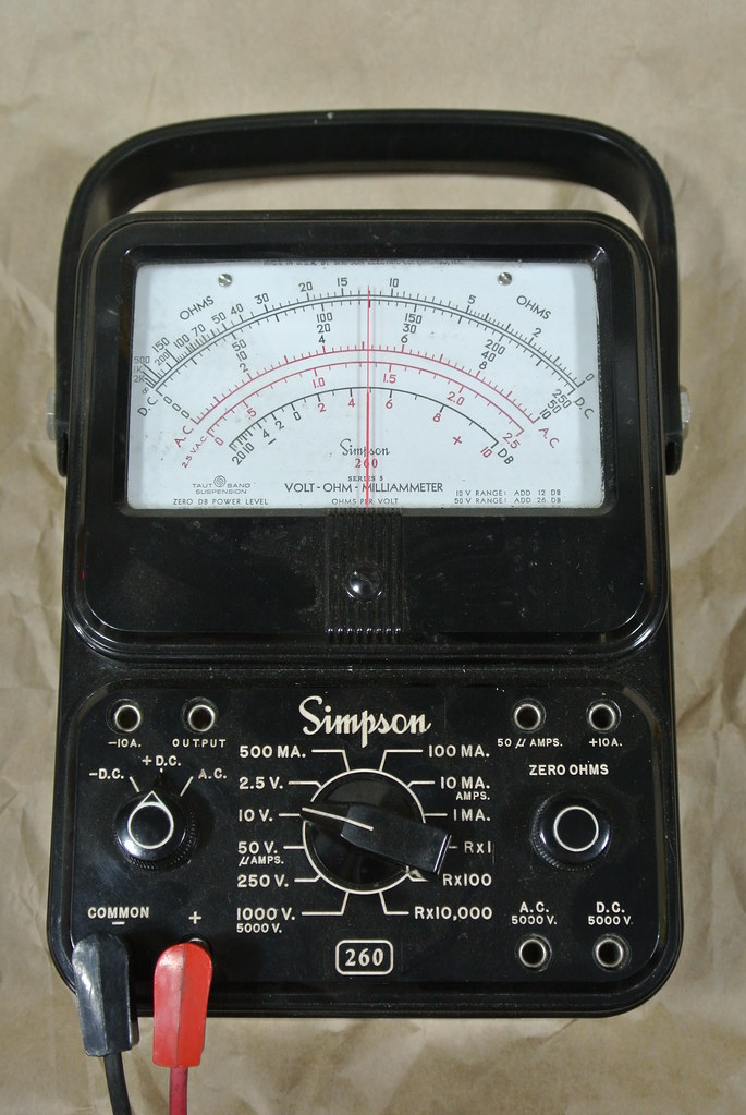
3.5.2 A vintage Simpson 260 or Weston
A genuine Simpson 260 VOM or a Weston panel instrument is the real-instrument aesthetic the whole genre chases — heavy bakelite or steel, a glass window, a long hand-lettered scale, the authority of laboratory gear. The collected build does not gut one; it imitates one, CNC-engraving a Simpson 260 face into a layered-MDF enclosure (Vol 1, Vol 8) precisely because a working Simpson is larger, pricier, and worth preserving rather than sacrificing. If you do build around a real vintage meter, treat it as a restoration: drive it gently within its range, keep the original scale if you can, and read Vol 8 before you touch the dial. A Simpson 260’s mirrored 50 µA movement is a beautiful thing to waste.
3.5.3 Edgewise, bargraph, and illuminated VU meters
Beyond the rectangular panel meter sit the edgewise meters (tall, thin, a needle on a vertical or horizontal edge), bargraph LED arrays (not moving-coil at all — a different clock), and illuminated VU meters with their warm backlight and printed “VU” arc. VU meters are moving-coil and re-faceable, and their defined ballistics (the standardized 300 ms rise/fall that gives a VU meter its characteristic lag) can make for an especially smooth seconds sweep — but those same ballistics are a fixed mechanical damping you cannot easily change, so confirm the movement’s (I_{fs}) (often driven through a rectifier and buffer in audio gear) before assuming it drops onto a pin. Edgewise meters re-face like any other; the look is mid-century rather than laboratory.
3.6 Where to buy, and a buyer’s checklist
The good news from §3.1 — that you want low full-scale current — also makes sourcing easy, because cheap DC microammeters and milliammeters are made by the thousand.
3.6.1 Where to look
- AliExpress / Amazon — new panel meters. Search “DC 0.5mA analog panel meter”, or by the common model family “85C1” (then “DC 100uA” / “DC 1mA” as you like). This is where the friendly 50 µA–1 mA movements live, a few dollars each, and where to buy your matched set of three (§3.4). Filter listings by the DC current ranges.
- Surplus / hamfest / electronics-surplus dealers. Bins of pulled panel meters — bare microammeters, edgewise meters, the occasional VU meter — often for less than new and sometimes with the (R_m) printed on the back. Inspect before buying (below).
- eBay — vintage Simpson / Weston. The place for a real Simpson 260 or Weston panel instrument if you want §3.5.2’s aesthetic. Buy on condition and completeness; a working movement with intact glass and pointer is worth more than a cosmetic shell.
3.6.2 The buyer’s checklist
Before you buy, confirm — from the listing, the back-of-meter label, or the seller:
- Full-scale current (I_{fs}) — the first filter. Aim ≤ 1 mA for direct-from-pin drive (§3.1); 10 mA+ means a buffer (Vol 4). This is non-negotiable; if it is not stated for a “DC mA/µA” meter, ask.
- Internal resistance (R_m) — nice to have, often omitted on cheap meters. If two will sit side by side, matched (R_m) is worth seeking (§3.2.1).
- Size — the cutout/bezel dimension. Three meters must fit your planned panel, and a 0–60 scale needs enough arc length to letter legibly (§3.3.2).
- Zero-adjust present — the small screw under the pivot that sets the mechanical zero. You will use it on every meter; confirm it is there and intact.
- Glass vs plastic window — cosmetic, but it sets the whole look (§3.5). Glass reads as instrument; plastic reads as modern.
- Buy three of the same model for a three-meter clock (§3.4) — and one spare if the listing is cheap, because matched batches go out of stock.
With (I_{fs} \le 1\ \text{mA}), a stated or measurable (R_m), a working zero-adjust, and three matched units in hand, you have meters your driver can reach and your calibration can align — and you are ready for Vol 4, where the resistor (or the buffer) that turns a PIC pin into a needle position gets sized for real.
References
- Vol 1 (Overview & Decision Tree) — the four build paths, the 0.5 mA decision, the two-meter “So Analog” parts.
- Vol 2 (How a Moving-Coil Meter Works) — d’Arsonval physics, (I_{fs}), (R_m), the voltmeter/ammeter relations underneath Figure 3.2.
- Vol 4 (Driving the Meter) — series-resistor sizing, the 25 mA pin limit, voltage-to-current buffers, calibration.
- Vol 5 (Timebase & Counting Logic) — the per-meter scale-adjust trims stored in EEPROM.
- Vol 8 (Dials, Faces & Enclosure) — MeterBasic re-facing, pivot geometry, preserving a vintage instrument.
- Two-meter “So Analog” parts (0–24 HOURS, 0–60 MINUTES re-faced plastic-bezel panel meters) held in
02-inputs/Simpson/.
Comments (0)