Steampunk · Volume 6
Mounting a Display Safely Inside a Decorative Case
Where the styling meets the hazard — standoffs, venting, clearance, bonding, and the finishes that quietly break an earth connection
This is the volume where the treatment stops being a matter of taste. Everything in Vols 3 to 5 was reversible: a finish can be stripped, a bezel can be changed, a case can be re-made. The decisions in this volume are the ones that determine whether the finished object is safe to hand to somebody who does not know what is inside it, and they are not reversible in the same way, because by the time the clock is assembled and lacquered the wiring is buried and the brasswork is on. A steampunk enclosure is a high-voltage enclosure first and a decorative object second, and the order of those two words is the whole content of this volume.
The hazard belongs to the display, not to the styling. A steampunk shell over a numitron, a meter movement, or a low-voltage LED display is an ordinary woodworking and metalworking problem with no electrical hazard worth the name. A steampunk shell over a nixie display sits in the hub’s high tier — an anode supply of roughly 150–200 V DC, sustained rather than transient, and still present in the reservoir capacitors after the clock is unplugged. A steampunk shell over a scope or CRT display sits in the highest tier — supplies from several hundred volts to several kilovolts, stored charge after power-off, and an evacuated glass envelope that can implode. The collected copper-pipe build in this subproject carries its author’s own warning that the circuit raises the voltage to a deadly 300 V and that contacts must not be touched while working; that is the right register for the whole subject.
The shell changes none of that. What it changes is who comes into contact with it, which is the subject of § 6.1.
6.1 What a decorative shell actually changes
Three things, each of which makes the underlying hazard more likely to reach a person rather than less.
It converts equipment into furniture. An unfinished board on a bench is treated as what it is. A finished brass-and-walnut object is picked up, turned over, dusted, carried to another room, and handed to a guest. Finishing is precisely the operation that removes the visual cues that say “this is dangerous,” and it does so deliberately and well.
It introduces conductive structure at the surface. Brass, copper, and steel are the signature materials of the aesthetic and all of them are conductors. Bezels, skins, pipe, bolt heads, hinges, corner brackets, handles, and feet are all things a hand lands on.
It applies pressure in the wrong direction on every clearance. Every decorative instinct — tighter, smaller, hide the cable, close the vent, fill the gap — works against creepage, clearance, and convection. The hub-wide baseline states this explicitly: do not compromise spacing for a tighter enclosure.
6.2 What this volume deliberately does not cover
The electrical discipline of working on a high-voltage clock is documented once, in the
display dives, and is not restated here. Specifically, the discharge procedure, the
sizing and fitting of bleeder resistors, measuring a high-voltage rail safely,
the one-hand rule and isolation-transformer practice, NOS tube handling, and the
first-power-up sequence live in the Nixie series’ safety volume and the Scope/CRT
series’ safety, calibration and troubleshooting volume, over the hub-wide baseline in
_shared/safety.md.
This volume assumes those have been read. It covers only what is specific to putting a display inside a decorative case: how the boards are held, how the air moves, how the metalwork is treated, how far things sit apart, and how the finish interacts with all of it. A builder who reads this volume instead of the display’s safety volume has read the wrong half.
6.3 Floating the high-voltage board
The high-voltage board is the one component whose mounting is not a matter of convenience.
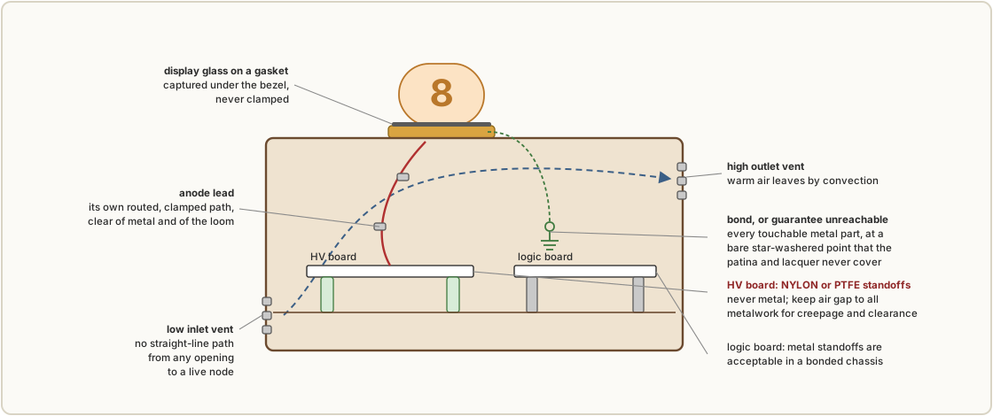
Insulating standoffs, not metal ones. The board carrying the boost converter, the reservoir capacitors, and the anode rail is mounted on nylon or PTFE standoffs with a generous air gap to any metalwork. Metal standoffs are acceptable for a logic board in a bonded metal chassis and are not acceptable here. In a wooden or printed case the same rule applies, because the standoffs also set the gap that § 6.6 depends on.
An insulating tray in a conductive or printed case. Where the case is metal, or where a printed wall might soften, give the HV board a printed or cut tray of its own in PETG, ABS, or a comparable material rather than relying on the standoffs alone. A wire that works loose should land on plastic, not on the chassis.
Orient for heat and for reach. Put the tall, warm, high-voltage components where convection can carry heat up and out of the outlet vent, and where their terminals face away from the surface a hand will open. The test is simple and worth applying literally: when the back panel comes off, what is a reaching hand nearest to? If the answer is a reservoir capacitor terminal, the layout is wrong regardless of what the bleeder does.
Strain-relieve the anode lead. It carries the highest voltage in the clock. Run it as a single well-insulated wire on its own path, clear of metalwork, clamped so that a tug or a vibration lands on the clamp rather than on a solder joint, and never bundled with low-voltage wiring.
6.4 Ventilation
A sealed decorative box will run warm — the converter and any dropping resistors dissipate real power — and the bell jar of Vol 4 § 4.4 is the worst case in the whole archetype set. Ventilation is therefore a requirement. It competes directly with two other requirements: keeping fingers and conductive objects out, and not spoiling the object.
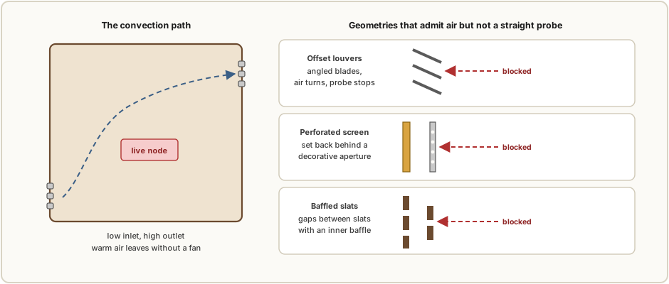
The resolution is convection venting: a low inlet and a high outlet, so warm air leaves on its own without a fan. The geometry then has to satisfy the finger-proof test.
The finger-proof test. No straight-line path through any opening should reach a live node. The practical version is that vent slots should be narrower than a probing finger and should be offset, louvered, or baffled so that a straight object pushed through is deflected. A paperclip, a curious finger, and a pet’s whisker are the canonical intruders.
Period-correct geometries that pass. The aesthetic is unusually well served here, because several genuinely traditional vent treatments are also good engineering: louvers stamped or milled into a panel, which are offset by construction; a perforated brass screen behind a decorative aperture; the gaps between decorative slats, which read as cabinetry; and finger-proof vents printed directly into a wall where the case is additively manufactured. The collected material shows fluted and finned case sides on a number of builds; where those flutes are open they are doing this job, and where they are cosmetic they are a missed opportunity.
If a fan is used, make it a quiet low-RPM unit on a filtered inlet, and bond its metal frame to the chassis ground. A fan is a last resort in a decorative object, because it is audible in a quiet room in a way a clock should not be.
6.5 Conductive structure: bond it, or guarantee it unreachable
This is the rule that most often decides whether a steampunk build is safe, because the aesthetic supplies so much metal.
There are exactly two defensible philosophies, and the danger is in drifting between them.
A bonded conductive case. Every piece of exposed metal a user can touch — the brass skin, the bezel, the bolt heads, the pipe, the feet — is bonded together and connected to protective earth, so that a fault puts current into the earth conductor and trips the supply instead of waiting for a hand. This is the right answer for a metal-bodied build and for the pipe-frame archetype of Vol 4 § 4.5, whose structure is conductive throughout.
A fully insulated case. The user-touchable shell is non-conductive — wood, acrylic, glass — and nothing that a user can touch can become live, so no earthing is relied on. The hardwood plinth of Vol 4 § 4.3 is the natural home of this philosophy, and it is the most forgiving topology available.
The dangerous build is the mixed one. A wooden or printed box with handsome floating brass bezels and brass bolt heads bonded to nothing is the characteristic failure: a single chafed anode lead turns the trim into a charged, isolated electrode waiting for a finger. The rule is stated as an absolute because it functions as one — bond the metal, or guarantee by construction that no live node can ever reach it, and never neither.
Bonding has to be real to count. A ring terminal under a star washer, on bare metal, at each panel, with continuity measured rather than assumed. Which leads directly to the collision in § 6.9.
6.6 Creepage and clearance in a decorative box
Two distances govern high-voltage layout. Clearance is the shortest path through air between two conductors. Creepage is the shortest path across the surface of an insulator between them. High voltage arcs across insufficient clearance and tracks — carbonises a permanent conductive path — across insufficient creepage, and tracking is much likelier on a surface that is dusty, humid, or contaminated.
At a nixie’s 150–200 V the distances required are modest; at a CRT’s kilovolts they are not. Either way, the enclosure’s job is the same: provide the room those distances need. That is a design input, not a constraint to be optimised away, and it is the single best argument against cramming a clock into the smallest possible case.
The enclosure-level practices that follow:
- Keep the converter output, the reservoir capacitor terminals, and the anode bus physically clear of the chassis and of the signal wiring.
- Where a wire must pass near grounded metal, give it slack and route it away rather than along the metal.
- Leave no sharp wire ends and no unfiled burrs anywhere in the high-voltage zone. Points concentrate field and promote corona and arc-over — which is a second, quieter reason to deburr every hole and edge beyond the cosmetic one in Vol 4.
- Remember that the decorative metalwork is itself one of the conductors the distances are measured to.
6.7 The exposed build
The open frame, the bare plinth, and the bell jar with the cloche lifted are the most dramatic and the most honest presentations in the aesthetic, and on a high-voltage display they are also the most hazardous: every live node, including the anode lead and the charged reservoir capacitors, is within reach.
The position this series takes is not a prohibition but a set of conditions. An exposed high-voltage build is defensible when it is treated as bench equipment rather than as furniture — kept where children and animals cannot reach it, not placed where it will be dusted or moved casually, and ideally fronted by a clear barrier that still shows the glass. It is not defensible as a coffee-table piece. The bell jar is a useful middle position precisely because it is a barrier that preserves the view, but it must be remembered that the jar lifts off and is therefore not an enclosure in the safety sense.
Where the display is low-voltage — numitron, meter movement, LED — none of this applies and the exposed build is simply a styling choice.
6.8 Harness segregation, strain relief, and service access
Good cable management in this context is a safety feature rather than tidiness, and the bell jar of Vol 4 § 4.4 makes it a visible one as well.
Three separated looms. Mains, high voltage, and low-voltage signal are routed as three physically separate bundles, each loomed or sleeved and tied down so nothing floats free to abrade or to fall against a live node. Sleeving is also the archetype’s friend: the collected lantern build ran a woven protective sheath over its 24-conductor ribbon for appearance, and the same sleeve does mechanical duty.
Mains entry to appliance standard. Where the clock runs directly from the mains rather than from an external low-voltage adapter — and the external adapter is the safer default, because it moves the mains transformer out of the touchable box entirely — the entry needs a properly clamped cord or an IEC inlet with strain relief, a fuse on the live conductor, a mains-rated switch in the live conductor, and protective earth carried to the bonding point of § 6.5 by a connection that is the last to break if the cord is pulled.
Design the service access. The habit that prevents the worst accidents is to arrange the wiring so that opening the case does not expose a charged capacitor or a live terminal to a reaching hand. Keep service slack so a panel can be opened without straining a joint. Where a decorative fastener must be removed to reach a board, Vol 4 § 4.10’s point applies: make that fastener one that survives repeated removal.
6.9 Where finishing and safety collide ⚠
This is the specific interaction that a styling dive is obliged to flag, because neither a finishing guide nor an electrical guide would catch it on its own.
Patina, lacquer, paint, and the natural oxide on raw brass are all insulators. Every finishing process in Vol 5 — the liver-of-sulphur darkening, the gun blue, the catalysed lacquer, the wax — puts a non-conductive layer over the metal it treats. A bonding connection made through any of them is not a bonding connection. It may even measure plausibly on a meter at first and then degrade.
Three rules follow, and they are cheap if applied early and expensive if discovered late:
- Mask the bonding points before finishing. Decide where each earth connection lands while the metal is still bare, mask those spots, and keep them out of every chemical and coating step.
- Use a star washer at every bonded joint, so the washer’s teeth cut through any residual film into fresh metal.
- Measure continuity after assembly and after finishing, from each touchable metal part back to the earth point — not once, but as the final step before the case is closed.
The same collision appears in the other direction: a bare, masked contact point is a spot where corrosion will start, so it belongs somewhere sheltered inside the case rather than on an exterior face.
6.10 The pre-close-up checklist
Run this before the back panel goes on for the last time. It is enclosure-level only; the display’s own bring-up checklist is in its own safety volume.
- HV board on nylon or PTFE standoffs, with measured air gap to all metalwork.
- Anode lead on its own routed, clamped path; not bundled with signal wiring.
- Bleeder fitted across the HV rail (sizing per the display’s safety volume).
- No sharp wire ends or unfiled burrs anywhere in the HV zone.
- Mains entry, if fitted: strain relieved, fused on live, switched on live, earthed.
- Three looms separated, sleeved, and tied.
- Every touchable metal part either bonded to earth or demonstrably unreachable.
- Continuity measured from each bonded part to the earth point, after finishing.
- Convection path clear: low inlet, high outlet, nothing blocking either.
- No straight-line path from any opening to a live node.
- Opening the case does not present a charged capacitor to a reaching hand.
- Display glass captured through a compliant gasket or collar; no point loads.
- Service slack sufficient to open a panel without straining a joint.
6.11 References (Vol 6)
- Hub-wide safety baseline,
Clocks/_shared/safety.md— the hazard tiers, the rules every high-voltage build inherits, and the explicit instruction not to compromise creepage and clearance for a tighter steampunk enclosure. - Nixie Vol 10 (Safety) and Vol 9 § 9.3 (HV clearance and insulation inside the enclosure) — the ~170–200 V discipline, the discharge procedure, bleeder sizing, and the nixie-specific enclosure subset this volume generalises.
- Scope/CRT Vol 12 (Safety, Calibration, Troubleshooting & Cheatsheet) and Vol 11 § 11.2 — the kilovolt discipline, the implosion hazard, and the grounded-versus- insulated case argument this volume restates in its general form.
Steampunk Nixie Tube Clock(Instructables),02-inputs/— the builder’s own warning that the supply reaches a deadly 300 V, and the note that insulation at the tube connector had to be taken seriously to avoid a high-voltage short.Lantern-Clock.pdf,02-inputs/— the woven protective sleeving over the 24-conductor loom (§ 6.8), and the note that LED conductors were insulated specifically because a brass gear sat above them.- Vol 5 of this series — the finishing chemistry whose insulating by-products § 6.9 depends on.
Comments (0)