Steampunk · Volume 4
Enclosure Design & Joinery
Proportion, the five constructions, and how each one is actually cut, laminated, soldered, or gutted
The enclosure is where a steampunk clock stops being a mood board and becomes a piece of work. It is also the stage at which most of the object’s eventual quality is decided, because every finishing choice in Vol 5 and every safety accommodation in Vol 6 is constrained by a form that was settled earlier. This volume covers the deciding and the making: how the display’s own geometry sets the proportions before any aesthetic choice is available, how the five archetypes of Vol 1 § 1.5 are actually constructed, and what each construction demands of the shop. The two collected build write-ups carry most of the weight here, because they are the only sources in this subproject that document construction rather than merely depict it — one a laminated hardwood and brass lantern, the other a soldered copper pipe candelabra, and between them they cover the two most common structural approaches in the whole aesthetic.
4.1 The display decides the proportions first
Before any question of style, the display imposes a geometry, and the treatment has to accept it. The relevant facts belong to the display dives and are only summarised here.
A side-view tube — the upright-numeral nixie families, and most VFD and numitron tubes — is read through the side of the glass, from across a room, with the numerals standing vertically. It wants to sit above the case with the glass exposed, which makes the enclosure a low horizontal plinth or bar whose long face is the front. An end-view tube is read down its axis, at the stack of numerals, and wants either to lie flat on a tilted tray read from above or to stand in a recessed well. A round CRT wants a front panel with a circular aperture and enough depth behind it for the neck, the base socket, and the deflection wiring, which is why scope-clock cases are boxes and nixie-clock cases are slabs. A panel meter wants a flat vertical face.
Two numbers fall out of the tube choice and set everything else: the pitch — how far apart the tubes sit, bounded below by the need for fingers to seat them and for one tube’s side-glow not to wash into its neighbour — and the height at which the glass must be held. The display dives give the per-tube figures. The point for this volume is that the case’s front elevation is essentially determined before the first aesthetic decision, and a design that fights it will look wrong in a way that no amount of brass will fix.
4.2 Proportion, and the one focal point
Vol 2 § 2.6 offered the focal-point test; here is its geometric form. The lit display is the only self-luminous element in the object, and in a dark room it is the only thing visible. Everything else exists to frame it. Three proportional habits follow, and they are visible in the best of the collected work and absent from the worst.
Give the display a quiet field. A plain surface immediately around the tubes — unbroken wood, a clean brass panel, a dark mask — makes the glow read as bright. Detail crowded up against the glass competes with it at exactly the distance where the eye is already looking.
Put the mass low. A heavy base under a light display is the proportion every real instrument uses, and it is what makes the plinth archetype so reliable. It also happens to be the honest layout electrically, because the boards and the transformer are the heavy things and they belong at the bottom.
Let one edge be long. Period instrument cases tend to have one dominant dimension and a small number of controls ranged along it. A case that is roughly cubical with detail on every face has no composition.
4.3 The hardwood plinth
The dominant form in the collected material, the most forgiving safety topology available because the structure itself is an insulator, and the construction with the richest documented example on disk.
4.3.1 The laminated slab, locked with all-thread
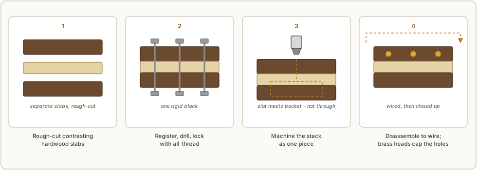
The collected lantern build solves the central problem of the hardwood plinth — how to machine a multi-part case accurately and still be able to take it apart to wire it — with a technique worth copying exactly. The builder began with contrasting stock, a walnut slab roughly 2 in thick and a maple slab roughly 1½ in thick, and intended to sandwich the two colours. Rough shapes were band-sawn and then brought to their outside and inside curves on a disc sander and a spindle sander.
The critical step came next. Through-holes common to every slab were registered and drilled, and lengths of all-thread rod were passed through them with washers and nuts, so that the stack could be mechanically clamped into a single rigid block. That block was then mounted in the mill and machined as one piece, guaranteeing that every feature — the wire routes, the compartment, the outer profile — lined up across the laminations. Afterwards the nuts came off, the stack separated for wiring, and the maple end pieces went back on with countersunk brass button-head fasteners, which conveniently covered the all-thread holes.
That sequence solves three problems at once: registration between parts, rigid work-holding for the mill, and serviceable disassembly. It is the single most transferable technique in the collected material.
4.3.2 Milling the wire routes and the electronics compartment
Two internal features have to be planned together, and the collected build is explicit about both.
The wire slot is milled deep enough that it intersects the electronics recess, so that the wire path opens into the compartment from inside. It is deliberately not a through cut, because taking it all the way through would badly weaken the shape once the compartment below is also removed. This is the kind of detail that only turns up in a real build write-up, and it is exactly why synthetic reference imagery is useless for construction.
The electronics compartment is laid out from the board rather than from the case: its outline is the circuit board’s outline plus room for the wires to enter and turn, and its depth is the board thickness, plus the clearance spacers it stands on, plus the tallest component on it, plus a margin. The compartment is then relieved around its rim with a shallow recess so the cover plate finishes flush — in the collected build, a 0.125 in cover plate into a pocket milled to 0.140 in. The cover itself can be anything rigid and thin; that builder used fibreglass circuit-board stock, and plywood is called out as an equally acceptable alternative.
Three habits go with this work. Clamp with wooden blocks against finished faces so the clamp never marks the wood. Plan the power-inlet position before the cover is cut, and prefer a right-angle plug so the inlet can be mounted facing down on the bottom cover. And remember that the compartment depth, once milled, is the hard ceiling on every component that will ever go in there.
4.3.3 Contrasting laminations and visible construction
The contrast between two woods — the collected build’s walnut and maple — is doing the work that applied ornament does in weaker designs. A visible glue line between two species, a through-fastener that is allowed to show, a chamfer that reveals the lamination: these are the Arts and Crafts argument of Vol 2 § 2.3.4 in physical form. They are also free, in the sense that they are consequences of how the object was made rather than additions to it.
4.4 The bell jar
Visually the strongest archetype in the collected gallery and structurally the simplest: a turned or laminated hardwood base, a glass cloche or bell jar sitting in a rebate turned into its top, and the entire movement standing on the base underneath.
The construction is nearly trivial; the difficulty is entirely elsewhere. Under a bell jar there is no back. Every board, every wire, every solder joint and every standoff is on permanent display from all sides, so the wiring harness stops being plumbing and becomes the visible mechanism — which is, after all, the point of the archetype. Practical consequences: use a tube-holder board and a driver board on standoffs so the stack looks deliberate; dress the harness into straight runs and tie it; consider sleeving ribbon cable, as the collected lantern build did with a woven protective sheath over its 24-conductor loom; and keep fasteners consistent, because mismatched hardware is very visible under glass.
Two constraints deserve naming. The jar is a sealed volume, which is the worst case for the convection venting of Vol 6 § 6.4 — the base has to carry the ventilation, and a build under glass with a warm supply needs that thought through rather than assumed. And the jar is glass over exposed electronics: it is a barrier against a casual hand, but it lifts off, so on a nixie or CRT build it must not be mistaken for an enclosure in the safety sense.
4.5 The pipe frame
Copper or brass tube, elbows, tees, flanges, unions, and valves used as the actual structure. The collected Instructables build is the worked example: a copper main tube carrying small soldered fittings, into which hooked tube holders are fitted, mounted to a solid mahogany baseplate that also houses the board.
The construction notes from that build are specific and worth carrying forward:
- The tube holders were fabricated, not bought — cut to length, expanded, and an existing triangular hole filed out to size, then the two parts soldered together.
- Shim rings were needed to fix the fittings concentrically to the main tube. That builder cut them from scrap PTFE, and then had to pin them with brass M3 screws precisely because PTFE is too slippery to stay put by friction. This is a small, real lesson: PTFE is a poor choice where a press or friction fit is doing the work.
- Wiring runs inside the pipe, threaded through the small fittings, with the cathode wires commoned and led down to the base. Running the harness inside the structure is the archetype’s great advantage — no visible cable at all.
Against that advantage, the pipe frame has two real drawbacks. It is a conductive structure throughout, which makes it the archetype most exposed to the bonding problem of Vol 6 § 6.5, and its interior is inaccessible once assembled, so the harness must be proven before closing up. That builder’s own note on the plug he had to develop — that there was no room between tube and brass socket, and that insulation had to be taken seriously or a high-voltage short would destroy the board — is the archetype’s characteristic hazard in one sentence.
4.6 Mounting the glass: a finding worth generalising
One detail from the copper build applies to every archetype and deserves to be lifted out of it. Holding a glass tube in a hard mount means bonding or clamping glass to something rigid, and the failure mode is not the bond letting go — it is the bond shrinking.
That builder cut tube seats from a laminate of red fibre and plywood, hole-sawn into discs and then opened up with a fretsaw against a printed outline taken from the tube’s datasheet. For fixing the tube into the seat, the reported result is explicit: a UV-cured resin worked best, because it hardens without creating tension against the glass envelope, whereas two-part resins and hot glue both build up stress as they shrink on curing and as they move thermally. A tensioned glass envelope is a cracked envelope eventually, and a cracked display tube is a dead one.
The general rule: anything that cures by shrinking, or that moves a lot with temperature, is the wrong material against display glass. Prefer a compliant mechanical capture — a printed collar, a silicone or cork liner, a gasket under a bezel — and where an adhesive is unavoidable, prefer one that does not shrink as it sets.
4.7 The conversion: gutting a donor chassis
The shortest route to a convincing object, because the proportions, the hardware, the panel graphics and the patina are already right and already consistent with each other. The collected donor material in this subproject is a vintage portable oscilloscope chassis, photographed in detail as a teardown; Vol 7 § 7.5 works through what those photographs show.
The method is straightforward and the cautions are not.
Survey before cutting. Photograph the interior comprehensively, from several angles, before removing anything — which is exactly what the collected donor set is. Those photographs are the only record of how the original was laid out, and they are what makes a reversible or a partial conversion possible later.
Decide what the donor contributes. Usually it is the case, the front panel, the bezel, the knobs, and the legend — not the electronics. Sometimes it is the display itself, when the donor is a scope and the CRT is good.
Respect the one-way door. A converted instrument is generally no longer restorable as an instrument. Where the donor is rare, complete, or working, that is a real cost; where it is a common, incomplete, or already-dead unit, it is not. This is a judgement to make deliberately rather than halfway through a Saturday.
Treat the old wiring as suspect. Vintage chassis carry rubber and cloth-insulated wire that has often gone hard and crumbly, wax-paper and electrolytic capacitors that have aged out, and in many cases a transformerless or otherwise unsafe mains topology. A conversion that keeps the old mains wiring inherits all of it. The safe default is to strip the chassis back to metal and re-wire completely.
Keep the panel honest. The most convincing conversions leave the original legend and let it be slightly wrong, rather than covering it. A panel that says what the instrument used to be is a better object than a panel that pretends the clock was always there.
4.8 The acrylic sandwich and the exposed build
Two laser-cut or CNC-routed plates separated by threaded standoffs, with the boards and the display captured between them. It is the fastest route from a drawing to a finished case, it is dimensionally precise straight off the machine, it is trivially iterated, and it is an insulator.
It is also, in the strict sense, not steampunk — it is the “honest exposed” style that sits alongside it, and the collected gallery holds a large number of commercial kit clocks in exactly this form. It earns its place here for three reasons: it is the ideal prototype case, in which the pitch, the height and the board stack can be proven before hardwood is cut; smoked or bronze-tinted acrylic doubles as a diffuser and a bezel; and the edge-lit acrylic plate is the standard way the underglow of Vol 3 § 3.6 is produced.
The safety caveat is Vol 6 § 6.7’s: an exposed build over a nixie or CRT supply leaves every live node within reach and should be treated as bench equipment, not furniture.
4.9 Fabrication routes
The constructions above map onto a well-equipped shop roughly as follows.
Table 1 — 4.9 Fabrication routes
| Construction | Primary operations | Typical equipment |
|---|---|---|
| Laminated plinth | Band-saw, disc and spindle sanding, drilling, milling pockets and slots | Bandsaw, sanders, mill or CNC router |
| Bell jar base | Turning or laminating, rebate for the jar | Lathe or router |
| Pipe frame | Cutting, deburring, soft-soldering fittings, drilling | Tube cutter, torch, drill press |
| Conversion | Disassembly, cleaning, panel drilling, re-wiring | Hand tools, step drills, nibbler |
| Acrylic sandwich | 2-D profiling only | Laser cutter or CNC router |
| Bezels, collars, rings | Turning, boring | Lathe; 3-D printing for fit-up |
Two workflow notes. Print the first case. Additive manufacturing is the cheapest way to prove tube pitch, bezel diameters, collar heights, and board clearances; the keeper is then re-made in wood, brass, or acrylic once the geometry is settled. And make the fit-up parts twice — printed collars and rings are consumables during fitting, and committing to a turned brass ring before the plastic one has been tried on is how material gets wasted.
4.10 Fastener and hardware discipline
The single cheapest way to lift a build, and the thing a viewer notices without knowing they noticed.
- Pick one family and stay in it. Brass pan-head or button-head throughout, or slotted throughout. The collected lantern build used 4-40 brass pan-heads through the bezels; its visible fasteners are all the same. Mixed plated and unplated, mixed drive types, and mixed head styles are the most common tell of an assembled-rather-than-made object.
- Slotted screws read as period; hex sockets do not. Slotted heads are fiddlier and mark easily, so drive them with a hollow-ground driver that fits the slot.
- Countersink, and cap. Counterbored fasteners capped by a subsequent part — the maple ends over the all-thread holes in the collected build — turn a construction necessity into a clean surface.
- Bezels are mounts. In the collected lantern build the acrylic tube’s diameter was chosen to equal the gauge-face diameter of the nickel-plated bezels, so that the bezels became the tube mounts rather than trim around them, four per fixture. That is the § 2.4 principle made structural.
- Leave a service path. Every decorative fastener that must come off to reach a board should be one that survives being removed repeatedly. Brass is soft; a screw that will be turned fifty times should be steel and hidden, not brass and visible.
4.11 References (Vol 4)
Lantern-Clock.pdf,02-inputs/— the laminated walnut-and-maple slab locked with all-thread for single-piece machining (§ 4.3.1), the milled wire slot deliberately not taken through and the board-derived compartment with its 0.125 in cover in a 0.140 in recess (§ 4.3.2), the woven sleeving over the 24-conductor loom (§ 4.4), and the bezel-as-tube-mount with 4-40 brass pan-heads (§ 4.10).Steampunk Nixie Tube Clock(Instructables, nine steps),02-inputs/— the fabricated hooked tube holders, the PTFE shim rings pinned with brass M3 screws, the wiring-inside-the-pipe construction (§ 4.5), and the UV-cured-resin-versus-shrinking- adhesive finding for fixing tubes into their seats (§ 4.6).- Donor-chassis photograph set,
02-inputs/Steampunk clock/ScopeInternals/, withwaterman_s11a_manual.pdf— the survey-before-cutting example of § 4.7; examined in Vol 7 § 7.5. - Sibling display dives for the geometry of § 4.1 — Nixie Vol 2 (tube families and viewing direction) and Vol 9 (mounting fragile glass), Scope/CRT Vol 6 (CRT selection) and Vol 11 (cradle mounting, bezel, mask and hood).
- Vol 6 of this series — venting, standoffs, clearance, and bonding, which constrain every construction above.
Comments (0)