Mechanical · Volume 4
Motors, Coils & Actuators
The drive layer — Lavet and stepper motors, the L293D and TMC2208 drivers, microstepping math, the tuning-fork sustaining amplifier, and hall-sensor homing
This is the hard part of the category. Vol 2 established that in a mechanical-movement clock the display is a position, and Vol 3 showed how a gear train turns one shaft into correctly paced hands. This volume covers the layer in between: the actuator that converts a microcontroller’s intent into actual motion, and the driver electronics that stand between a logic pin and a coil. Across the three collected builds the actuator takes three quite different forms — a stepper motor through an L293D (planetary) or a TMC2208 (aviation), and an electromagnetic drive-and-sense coil pair that keeps a steel fork ringing (tuning fork) — but all three are the same physics underneath: a current through a coil makes a magnetic field, and that field pushes on something. The friendly electronics of Vol 1 end here; getting a coil to move a mass precisely and repeatably is the craft.
4.1 The actuator family for clocks
Three actuator types cover essentially every electromechanical clock, and all three appear in this hub:
- The Lavet-type stepper inside every cheap quartz movement — one bipolar coil pulsed once per second, advancing a toothed rotor exactly one step. This is the most-produced electric motor on Earth and the baseline every other mechanism is measured against (§4.2).
- The multi-pole stepper — a unipolar 28BYJ-48 or a bipolar NEMA-17 at 1.8°/step (200 steps/rev). This is the workhorse of the maker clock: it positions a hand or needle to a commanded angle and holds it there. The planetary and aviation builds both use one (§4.3–4.6).
- The resonant electromagnetic drive — not a rotating motor at all, but a coil that delivers a tiny kick to a resonator (a tuning fork) once per cycle to replace the energy lost to damping, plus a second coil that senses the motion. The collected tuning-fork clock is the example (§4.7).
The first two move to a place; the third sustains an oscillation. That distinction — positioning versus sustaining — is the spine of this volume.
4.2 Background: the Lavet step motor in a quartz movement
Before the steppers the maker reaches for, it is worth understanding the motor the maker is replacing. Inside a one-dollar quartz movement is a Lavet-type stepping motor: a single bipolar coil, a stator with deliberately asymmetric notches, and a small permanent-magnet rotor magnetized across its diameter. The quartz/divider chain (Vol 5) issues one current pulse per second, and the coil’s field flips the rotor 180°; the stator notches break the magnetic symmetry so the rotor always relaxes to the next preferred angle rather than falling back. The polarity of each pulse alternates, so the rotor advances 180° per second in one consistent direction, and a tiny pinion drives the seconds wheel.
The Lavet motor is brilliant for what it is — sub-microamp average current, no driver chip beyond the divider’s output stage, decades of unattended running on one cell — but it has no position feedback and no holding torque to speak of beyond the detent of the notches. It can only ever count forward one tooth at a time. The maker clocks in this hub abandon it precisely because they need to command a position (sweep a needle to 9.40, point an hour hand at the right mark), which the Lavet motor cannot do. That requirement is what drives the move to a multi-pole stepper with a real driver.
4.3 Steppers: unipolar (28BYJ-48) vs bipolar (NEMA-17)
A stepper motor has many stator poles arranged so that energizing the phases in sequence advances the rotor a fixed angle per step. Two families dominate hobby clocks:
- Unipolar — the 28BYJ-48. A cheap geared 5-wire/6-wire motor, usually driven by a ULN2003 darlington-array board. The “unipolar” name means each coil has a center tap, so current only ever flows one direction through each half — the drive electronics are dead simple (just switch each half to ground) but you use only half the copper, so torque per watt is poor. The 28BYJ-48 hides this behind a large internal gearbox (commonly ~64:1), giving it decent output torque at the cost of speed and backlash. Fine for a slow-moving hand; not used in the collected builds, but the default first stepper most makers meet.
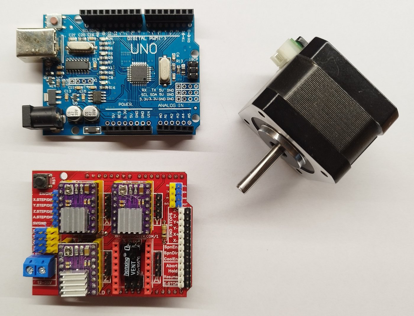
- Bipolar — the NEMA-17. The standard maker stepper: a 42 mm-square frame, two coils (four wires), no center taps, 1.8° per full step → 200 full steps per revolution. “Bipolar” means current must be driven both directions through each coil, which is why it needs an H-bridge per coil (§4.4). It uses all its copper, so torque density is far better than a unipolar motor of the same size. Both the planetary clock (a generic 1.8°/step NEMA stepper) and the aviation clock (three NEMA-17s) use bipolar steppers — the extra driver complexity is the price of the torque and resolution a clock movement wants.
The 1.8°/step figure is the number everything downstream is built on: 360° ÷ 1.8° = 200
full steps per revolution, and that 200 is the raw resolution before microstepping (§4.6) or
gear reduction (Vol 3) multiplies it.
4.4 Driving steppers: H-bridge basics and the L293D
To drive current both ways through a bipolar coil you need an H-bridge — four switches arranged in an “H” with the coil as the crossbar. Close the top-left and bottom-right switches and current flows left-to-right; close the other diagonal and it flows right-to-left; the four combinations give you forward, reverse, brake, and coast. A bipolar stepper has two coils, so it needs two H-bridges, and the controller energizes them in quadrature (A+, B+, A−, B−, …) to walk the rotor around.
The L293D, used in the planetary clock, is exactly that: a dual H-bridge in one 16-pin DIP, rated about 600 mA per channel (the related L293 is ~1 A), with the “D” suffix marking the built-in flyback clamp diodes that catch the inductive kick when a coil switches off. The Arduino toggles four logic pins (often two PWM enables plus direction) to step the motor through full-step (one or two phases energized) or half-step (alternating one- and two-phase, doubling the apparent resolution to 400 half-steps/rev) sequences.
Why the L293D is the simple-and-cheap choice for the planetary build:
- It is a bare H-bridge — no current chopper, no microstepping, no configuration. You feed it logic levels and it switches the rail. Easy to reason about, hard to misconfigure.
- It costs almost nothing and is socketed in a DIP, so a blown one is a 30-second swap.
- The planetary clock asks little of it: a printed gear train under a light hand load, moving in discrete commanded steps with a generous GT2 pre-reduction (Vol 3) ahead of it. It does not need silence, microstep smoothness, or precise current control.
Its limits are equally clear: there is no current limiting, so motor current is set only by the supply voltage and coil resistance (you cannot run a low-resistance motor hot-and-fast safely); the bipolar-transistor outputs drop ~1.5–1.8 V each, wasting power as heat; and there is no microstepping, so motion is in audible full or half steps. For a slow clock hand none of that matters — which is precisely why it is the right tool there and the wrong one for the aviation gauges.
4.5 A modern driver: the TMC2208 (aviation)
The Aviation clock drives three NEMA-17s through TMC2208 modules — a generational jump from the L293D. The TMC2208 is a current-controlled microstepping driver: instead of just switching the rail on and off, it regulates the actual coil current with a chopper and synthesizes intermediate current levels to place the rotor between full steps. Three features matter for a clock:
4.5.1 Current set via Vref
You do not set current with the supply voltage as on an L293D. A trimmer on the module sets a reference voltage Vref, and the chip chops the coil current to the corresponding peak. Set Vref to match the motor’s rated phase current (a NEMA-17 is often ~1 A or less for this duty) so the motor runs warm, not hot, and the driver does not skip. This is the single most important setup step — too high cooks the motor and driver, too low loses torque and skips steps mid-sweep.
4.5.2 Microstepping
The TMC2208 divides each 1.8° full step into many microsteps by holding the two coils at sine/cosine-weighted current ratios. Smaller increments mean smoother, quieter motion and finer positioning — exactly what a swept gauge needle wants so it glides rather than visibly notching between marks. The microstep count is selected by two configuration pins, MS1 and MS2.
4.5.3 StealthChop quiet operation
The TMC2208’s headline feature is StealthChop, a voltage-PWM chopping mode that moves the switching noise out of the audible band. A bank of three steppers driven by L293Ds would whine on every sweep; under StealthChop the aviation gauges move silently, which is the whole point of a clock that sits on a desk. (StealthChop trades some high-speed torque for silence, which a slow-moving clock needle can easily afford.)
4.5.4 The MS1 / MS2 microstep table
From the Aviation schematic (Aviation/schematic01.jpg), the TMC2208 microstep resolution is
set by tying MS1 and MS2 to ground (GND) or logic (VCC_IO):
Table 1 — set by tying MS1 and MS2 to ground (GND) or logic (VCCIO)
| MS2 | MS1 | Microstep setting |
|---|---|---|
| GND | GND | 8 microsteps |
| GND | VCC_IO | 32 microsteps |
| VCC_IO | GND | 64 microsteps |
| VCC_IO | VCC_IO | 16 microsteps |
Note the ordering is not a simple binary count — both-low is 8 and both-high is 16, with the high-resolution 32 and 64 settings on the mixed states. (This pin map differs from some other TMC parts, which the schematic flags directly with its “different to TMC2208” annotations.)
4.6 Microstepping math and the torque trade-off
The positioning resolution of a microstepping stepper is:
microstep angle = full-step angle ÷ microstepsFor a 1.8°/step NEMA-17 at the 16-microstep setting (both MS pins to VCC_IO):
1.8° ÷ 16 = 0.1125° per microstepand the rotor now takes 200 × 16 = 3200 microsteps per revolution. Push to the 64-microstep
setting and it is 1.8° ÷ 64 = 0.028° per microstep, 12 800 microsteps/rev. That is the
motor-shaft resolution; the needle resolution is finer still by whatever gear reduction
sits between the motor and the gauge pointer:
needle resolution = microstep angle ÷ gear reductionSo a 16-microstep motor behind, say, a 4:1 reduction resolves the needle to
0.1125° ÷ 4 = 0.028° — far finer than the eye can read on a small dial (Vol 2), which is the
goal: the limit on readout accuracy should be the dial and the homing repeatability, never the
motor’s step grain.
The trade-off — microstepping does not give free torque or free accuracy. Two cautions:
- Incremental (holding) torque falls as microsteps rise. Full-step torque is set by the full coil current; at a microstep the current is split sine/cosine between the two coils, so the restoring torque per microstep is only a fraction of a full step’s. Microstepping smooths motion and reduces resonance, but the detent that holds a microstep position is weak — most of the motor’s holding ability still comes at the full-step boundaries. A heavily microstepped motor can be nudged off a microstep by friction or load far more easily than off a full step.
- Microstep position accuracy is not as fine as the math implies. Magnetic and mechanical imperfections mean the rotor does not sit at the exact ideal microstep angle. Past ~16 microsteps you are buying smoothness and quiet, not true positioning accuracy. For the aviation gauges that is exactly the right bargain — the needle glides silently and the absolute accuracy comes from homing (§4.8), not from counting microsteps.
The practical lesson: microstep generously for silky, silent motion, but never trust step counting alone for absolute position — home to a physical reference, then move a known number of steps from there.

4.7 The tuning-fork magnetic sustaining amplifier, in depth
The tuning-fork clock has no rotating motor at all. Its actuator is a pair of coils and a magnet that keep a steel 440 Hz fork — the clock’s actual timebase (Vol 5) — ringing indefinitely. The principle is the oldest one in horology dressed in electronics: a resonator loses a little energy to damping each cycle, so a sustaining mechanism must feed energy back in, in phase, once per cycle. A pendulum clock does it with an escapement; the Accutron did it with a coil and a single transistor; this clock does it with a two-stage transistor amplifier wired as an oscillator.
4.7.1 Sensing the fork — a guitar pickup
The fork is plain steel and has no field of its own, so the designer’s 3D-printed mount holds two 22 mH (11 mm) inductors and a 15 × 5 mm neodymium rod magnet in the base, with the fork tines vibrating in the magnet’s field. As a tine moves, it modulates the field through the nearby coils — exactly how a guitar pickup turns a vibrating steel string into a voltage. One coil is the sense coil; the other is the drive coil.
4.7.2 The amplifier loop
The loop, verbatim from the designer’s description, is:
- The sense coil’s tiny output is amplified by a single-stage common-emitter (CE) amplifier (a BC547 NPN — the board carries seven of them across all stages).
- The amplified signal passes through a passive bandpass filter centred roughly on 440 Hz. The bandpass does two jobs: it selects the fundamental (rejecting harmonics and noise so the loop locks onto the fork’s true resonance rather than an overtone) and it sets the loop phase so the energy arrives at the right moment in the cycle.
- The filtered signal feeds a second transistor amplifier that powers the drive coil.
- The drive coil pushes the fork in phase with its motion, replenishing the energy lost to damping. The output feeds back to the sense coil through the fork’s mechanical motion, closing a positive-feedback loop.
This is a Barkhausen oscillator — but the crucial twist is that its frequency-determining element is not an RC or LC network. It is the mechanical Q of the steel fork. The electronics merely supply gain and the right phase; the fork itself decides the frequency, and a precision steel fork has an enormously high mechanical Q, which is why a 440 Hz fork oscillator is far more stable than any transistor-and-capacitor oscillator at the same frequency. The bandpass is centred only “roughly” at 440 Hz precisely because it does not set the frequency — it only needs to be selective enough to keep the loop on the fundamental and to trim the phase.
4.7.3 Why it self-starts
The loop needs no kick-start. At power-on, broadband thermal/electrical noise is present at the sense coil; the component of that noise near 440 Hz passes the bandpass, gets amplified, and drives the fork a hair. Because the loop gain at the fork’s resonance exceeds unity (the Barkhausen condition) and the fork’s high Q makes the feedback at 440 Hz overwhelmingly the strongest, the oscillation builds up from noise until amplifier limiting holds it at a steady amplitude. The designer notes that at 5 V the circuit is sensitive enough to be self-starting — no tapping the fork to get it going, unlike a low-gain sustaining circuit.
4.7.4 The numbers, and the BNC tap
The circuit is remarkably frugal and robust:
- It draws around 1 mA.
- It self-starts at 5 V (the clock’s regulated rail, from an L7805).
- It sustains oscillation down to less than 3 V — so a sagging supply dims the displays long before the timebase quits.
An on-board panel-mount BNC connector taps the sense-coil amplifier output, so a scope
can watch the raw pickup waveform — the analog heartbeat of the clock — while it runs. From
there the analog signal is squared by an NE555 into clean logic-level pulses for the
ATtiny4313 to count (the count, 440 × 60 = 26 400 pulses/minute, is Vol 5’s subject).
4.7.5 The factory-inconsistent inductor polarity gotcha
The one assembly trap, called out in both the designer’s article and the build README: the polarity of the two inductors is not consistent from the factory. Because the loop only sustains when the drive coil pushes the fork in phase, a coil wound the “wrong” way inverts that drive and the fork barely moves (the feedback fights the motion instead of reinforcing it). The fix is empirical and easy: flip one inductor, or flip the magnet. Reversing either one flips the relative sense of drive-versus-pickup and “usually results in much better vibration of the fork.” If a freshly built board hums weakly or refuses to start, this — not the amplifier — is the first thing to check.

4.8 Hall-effect homing — giving a stepper an absolute zero
A stepper or a swept needle has a fundamental blind spot: it has no idea where it is at power-on. It can count steps relative to wherever it happened to start, but it has no absolute position — and a clock that does not know where its hands are cannot tell the time. This is the homing problem Vol 2 raised, and the planetary and aviation builds solve it the same way: a hall-effect switch plus a magnet defines a physical zero.
4.8.1 The A3144 / 3144E open-collector hall switch
Both builds use the same part family — an A3144 (planetary) or 3144E (aviation) hall switch. It is a digital, open-collector sensor: when no magnet is near, the output floats (held high by a pull-up); when a magnet of the correct polarity comes close enough, the internal comparator trips and the output is pulled low. It is a clean on/off “magnet present” switch, not an analog field reading — exactly what you want for a hard zero reference. A small neodymium magnet is mounted on the rotor / carrier / gauge wheel, positioned so it passes the fixed hall sensor at one defined angle.
4.8.2 The homing routine
On power-up the firmware runs the same sequence on each axis (the planetary carrier, or each of the three aviation gauges, which carry one 3144E per gauge):
- Step the motor slowly in one direction.
- Watch the hall output every step.
- Stop the instant the hall switch trips (output goes low) — the magnet is now at the sensor.
- Declare that position “zero.” From here the step count is absolute: every commanded position is “home plus N steps,” and the time can be read true off the dial.
Without this, a power blip would leave the hands or needles pointing at a random offset forever. With it, the clock re-establishes truth in a second or two at every power-on — and, because the absolute reference is a physical magnet-and-sensor, it does not drift with accumulated step error the way pure step-counting would (§4.6). This is why the rule from Vol 3 is “home once, then slave the steps to the timebase”: the hall sensor fixes the origin, the timebase (Vol 5) fixes the rate.

4.9 Two motion regimes: continuous rotation vs point-to-point
The collected builds split cleanly into two ways of using an actuator, and it is worth naming the difference because it drives the firmware as much as the hardware:
- Continuous rotation (planetary, geared). The planetary clock’s motor turns essentially one direction, slowly and continuously, and the gear train (Vol 3) reduces that rotation into hour and minute hands. Homing happens once at start-up to fix the origin; thereafter the firmware simply keeps the hands moving forward at the rate the DS3231 dictates. Backlash and smooth advance matter; absolute repeatability of intermediate positions does not, because the train only ever goes forward.
- Point-to-point positioning (aviation gauges). Each aviation needle must home, then go to a specific commanded angle — sweep to “9” for the hour, jump to a new minute, advance the second — and may move in either direction. Here the per-axis hall sensor, the microstepped smoothness, and the StealthChop silence all pay off: the needle must arrive at an exact angle, settle without overshoot or audible chatter, and be trusted to read true against the printed dial. This is the “home-then-go-to-angle” regime, and it is why the aviation build spends the extra cost on TMC2208s where the planetary build is happy with an L293D.
The tuning-fork clock belongs to neither regime — its actuator does not position anything; it sustains a resonance. That is the conceptual reward of this volume: “actuator” in a mechanical clock can mean a motor that goes to a place or a coil that keeps something ringing, and the collected hub holds one of each. The counting and timebase logic that sit on top of all three — dividing the DS3231 down, counting the fork’s 26 400 pulses/minute, fetching NTP time for the gauges — is Vol 5.
References
- Cross-references in this series: Vol 1 (the three threads and their anchor builds), Vol 2 (how a position reads as a time — the homing/repeatability problem this volume answers), Vol 3 (the gear reduction ahead of the planetary actuator and the “home once, then slave to the timebase” rule), Vol 5 (the DS3231 timebase, the fork’s 26 400-pulse/minute count, and the NTP/counting logic that commands these actuators), Vol 6 (the build sequence — wiring the drivers, setting Vref, the coil polarity check), and Vol 9 (the file-by-file walk-throughs of the PlanetaryGear, TuningFork, and Aviation designs).
Comments (0)