Mechanical · Volume 2
The Readout — Hands, Dials & Needles
How a mechanical position encodes time across three threads, and the reading concerns — parallax, resolution, backlash, and zeroing — that come with a display you have to move
Every clock in this hub answers the same question — what time is it? — but the Mechanical category answers it without a single glowing segment. The readout here is a position: where a hand sits on a dial, what angle a needle points to behind an instrument bezel, which of five seven-segment digits the fork’s own vibration has clocked out. Vol 1 made the headline claim that position is the display; this volume is the one that takes that claim apart and shows the mechanics of it — how a position encodes a time, and what that choice costs you at reading time that a nixie tube or a Numitron never has to pay.
The three collected builds span the full range of how a mechanical position can carry a number. The PlanetaryGear clock is the purest case: two hands swept continuously around a conventional 12 h / 60 min dial by a gear train, the four-thousand-year-old reading convention. The Aviation clock takes the same idea — a needle at an angle — but drives it digitally, in fine microsteps, behind an aircraft instrument face, so the needle that looks analog actually lands on a grid of discrete positions. The TuningFork clock is the outlier that proves the rule: its timebase is mechanical (a humming steel fork) but its readout is fully digital — five seven-segment displays — and the builder then went out of his way to make that digital readout look mechanical and strange, with a custom glyph set and the displays mounted upside down. Three threads, three answers, one shared set of headaches.
2.1 Encoding time as a position — the three threads
2.1.1 Analog hands on a dial — the PlanetaryGear clock
The dial-and-hands convention is so familiar it is easy to forget it is an encoding. A circular dial maps an angle to a number by fiat: the minute hand makes the full circle — 360° — stand for one hour, and the hour hand makes the same full circle stand for twelve hours. Two hands on concentric shafts, turning at a 12:1 ratio, let one face show hours and minutes at once. The collected PlanetaryGear clock realises exactly this:
- the minute hand turns 1 revolution per hour (360° / 60 min = 6° per minute), and
- the hour hand turns 1 revolution per 12 hours (360° / 12 h = 30° per hour, or 0.5° per minute).
The whole engineering problem of that clock — the planetary gear train, the GT2 belt pre-reduction, the math worked in Vol 3 — exists only to pace those two shafts at that ratio from a single 1.8°/step stepper. From the reader’s side it is the oldest readout in the world: you do not read a number, you read two angles and round.
The defining property of the geared hand is that it moves continuously. The stepper underneath advances in 1.8° increments, but it is geared down so hard (see Vol 3) that the hand’s motion at the tip is smooth to the eye — the quantisation has been divided away into invisibility. A geared analog hand is therefore the one readout in this hub with effectively infinite angular resolution at the display; its accuracy is limited by the timebase (the DS3231) and by mechanical error (backlash — §2.3.3), not by the size of a step.
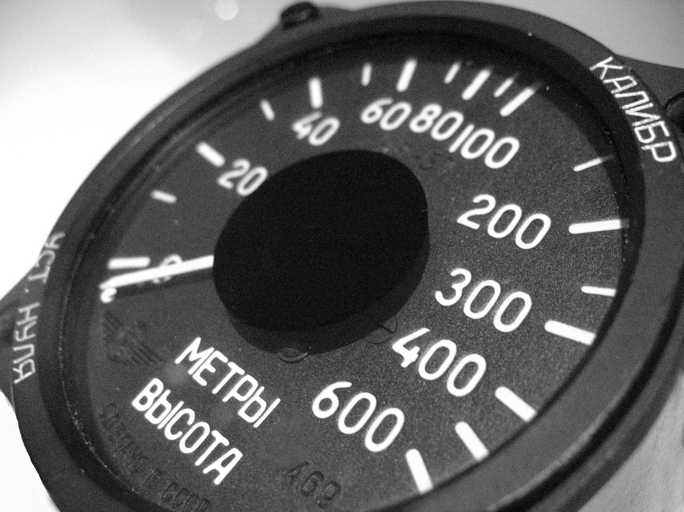
2.1.2 A needle angle on an instrument gauge — the Aviation clock
The Aviation clock keeps the angle-encodes-a-number idea but throws away the round 12 h face and the concentric-hands convention. Instead it borrows the look of an aircraft instrument: three separate printed gauge dials, one each for seconds, minutes, and hours, each with a single needle that sweeps an arc. Where a clock dial is fixed by tradition at 360° = 12 h, an instrument gauge can map its quantity onto whatever sweep angle the dial art draws — a typical instrument needle covers something like 270° of useful travel, not the full 360°, with the dead zone at the bottom hidden behind the bezel.
So the encoding here is a designer’s choice baked into the printed dial face and the firmware together:
- the seconds gauge maps 0–60 s onto its needle sweep,
- the minutes gauge maps 0–60 min onto its sweep, and
- the hours gauge maps 0–12 h (or 0–24) onto its sweep.
Each needle is driven by its own NEMA-17 stepper through a TMC2208 microstepping driver and a gear/rotor reduction (Vol 4). The firmware knows the gauge’s full-scale sweep and the gear ratio, computes the microstep count for “this many seconds,” and commands the motor there. Unlike a real moving-coil meter — which deflects by physics, an analog current balancing a spring — this needle lands where the step count puts it. That is the whole reason the Aviation clock lives in the Mechanical hub and not the Meter-Movement one (Vol 1, §1.3): its readout is a gear-and-motor position, not an electrical deflection.
2.1.3 A digital segment row from a mechanical timebase — the TuningFork clock
The TuningFork clock inverts the whole premise. Where the other two have a mechanical indicator and an electronic timebase, the fork clock has a mechanical timebase — a 440 Hz steel fork that is the reference oscillator (Vol 5) — and a digital indicator: five seven-segment displays (the collected build uses SC39-11YWA modules; the schematic family is the SC56-51PBWA / SC39-11YWA 7-segment data sheet referenced in Vol 9). The ATtiny4313 counts fork pulses (440 × 60 = 26 400 pulses per minute) and a 74HC595 shift register scans the digit row.1
There is no hand, no needle, no angle. Time is read as digits, the way you would read a nixie or Numitron clock — except that the number on the glass is being clocked out by the mechanical resonance of a vibrating fork rather than by a quartz crystal. This is the build that most sharply makes Vol 1’s point that what keeps time and what shows time are separate subsystems: here they have been swapped relative to the other two clocks. And as §2.4 covers, the builder then deliberately roughened the readout — an obscure glyph set, inverted displays, a segment “progress bar” — so that even this digital display refuses to read like an ordinary clock.

2.2 Continuous vs quantized — what actually moves
The three readouts sit at three different points on a spectrum from perfectly continuous to perfectly discrete, and that placement decides what “resolution” even means for each.
2.2.1 The geared hand — continuous (quantisation divided away)
A gear-driven hand is mechanically continuous. The 1.8°/step stepper is itself quantised — 200 steps per revolution — but the planetary reduction between motor and hand is so large that one motor step moves the minute-hand tip by a tiny fraction of a degree. Whatever residual stepping exists is far below what the eye or the dial graduations can resolve, so for reading purposes the hand is continuous: it can indicate any time between graduations, and you interpolate by eye exactly as you would on a quartz wall clock.
2.2.2 The gauge needle — finely quantized (microsteps)
The Aviation needle is the interesting middle case: it looks continuous but is actually quantized to microsteps. This is the direct forward-link to Vol 4’s microstepping treatment. The angular resolution at the motor shaft is:
motor step angle       = 1.8° / full step      (200 full steps / rev)
microsteps per step    = 16   (typical TMC2208 setting)
microsteps per rev     = 200 × 16 = 3200 microsteps / rev
angular resolution     = 360° / 3200 = 0.1125° per microstep   (at the motor shaft)
Then the gear reduction between motor and needle divides that down further — the needle moves even less per microstep than the motor does. The general rule, carried forward to Vol 4:
needle angular resolution = (step angle ÷ microsteps) ÷ gear reductionSo the needle is quantized, but the least count is small enough that the eye reads it as smooth motion. The worked numbers — and what 0.1125°/microstep means for placing “60 seconds” across an instrument dial sweep — are §2.5.
2.2.3 The segment row — fully discrete
The seven-segment readout is digital and so is fully quantized by construction: it can only ever show whole units of its least significant digit. The fork clock’s five digits show hours and minutes (and the builder uses the lowest digit’s segments as a per-minute progress bar, §2.4.3), so the readable least count is one minute — there is no interpolation and no “between.” A digit is on or off; the question of angular resolution simply does not arise. What does arise instead is the timebase question (Vol 5): the digits are only as honest as the fork’s pulse count is accurate.
2.3 Reading concerns unique to a mechanical readout
A glowing-tube clock has exactly one reading concern: can you see the digit? A mechanical position-readout inherits a whole family of error sources that come specifically from the fact that you have to move a physical thing to a physical place and then read an angle off it. These are the concerns Vol 1 flagged as defining the category.
2.3.1 Parallax
Because a hand or a needle sits a few millimetres above the printed dial, reading it from an angle shifts the apparent position against the graduations — parallax error. It is worst on the gauge clock, where the needle stands proud of a deeply printed instrument face, and on any build with a thick bezel or a domed crystal. Real aircraft instruments fight this with knife-edge needles and mirrored dial arcs (you line the needle up with its own reflection to read square-on); a printed clock can borrow the trick by keeping the needle close to the face and reading it head-on. The seven-segment fork clock is the only one of the three with no parallax — a flat digit has no height to shift.
2.3.2 Angular resolution / least count
The least count is the smallest time difference the readout lets you distinguish. For the geared hand it is set by the dial graduations (how finely the minute ring is printed) since the hand itself is effectively continuous. For the gauge needle it is set by both the dial graduations and the microstep resolution through the gearing (§2.5) — whichever is coarser dominates. For the segment row it is the least significant digit — one minute. A design mistake common to needle clocks is graduating the dial finer than the microstep resolution can actually place the needle, promising a precision the mechanism cannot deliver.
2.3.3 Backlash as a reading error
Backlash — the slack between meshing gear teeth, covered mechanically in Vol 3 — shows up at the readout as a direction-dependent position error. When the train reverses, the driving tooth must cross the gap before it re-engages the driven tooth, so the hand or needle lags by the backlash angle until the slack is taken up. On a continuously forward- running clock this mostly hides (the train only ever pushes one way), which is why the PlanetaryGear and the seconds/minutes/hours gauges are designed to advance monotonically. It bites hardest during homing (§2.3.4), where the mechanism may approach the zero from one direction and then run from it in the other — so good homing routines always approach the zero from a consistent direction to make the backlash a fixed, calibrated offset rather than a random one. Backlash is invisible on the segment readout: there are no gears between the counter and the digit.
2.3.4 The homing / zeroing problem — the big one
This is the concern that has no analog in a tube clock at all. A nixie always knows it is showing a “7”; the cathode is either lit or not. But a hand or a needle has no absolute sense of where it is. A stepper motor is an incremental device — it knows only “I took N steps from wherever I started,” not “I am pointing at 3 o’clock.” Power the clock off and move the hand by hand, or lose count by a missed step, and the readout is now wrong by an unknown amount and has no way to know it.
The fix is homing: on power-up, the mechanism drives until a sensor tells it the indicator is at a known reference position, then zeroes its step counter there and counts forward from that absolute origin. All three position-readouts in this hub solve it with a Hall-effect sensor and a small magnet:
- the PlanetaryGear clock homes once on startup with an A3144 hall sensor and a neodymium magnet on the train, establishing the 12-o’clock origin;
- the Aviation clock homes each of its three gauges independently with a 3144E hall sensor per gauge, so every needle finds its own zero on power-up.
The sensor + magnet hardware and the homing routine itself (approach direction, debounce, the backlash-consistent re-approach) are Vol 4’s territory; the point here is that homing is what makes a position-readout trustworthy. Without it, a mechanical clock is a clock that forgets the time the instant you unplug it. The fork clock, again, sidesteps the whole issue — a digital counter has nothing to home; it just needs the count to be right.
2.4 The fork clock’s unusual readout — Elian script, inverted displays, a progress bar
The fork clock’s readout deserves its own section because the builder made three deliberate, unusual choices that have nothing to do with timekeeping and everything to do with aesthetic — choices that turn a plain five-digit display into something that reads like a piece of personal cryptography.
2.4.1 Why an obscure glyph set at all
The standard reason to drive a seven-segment display is legibility: anyone can read
12:45. The fork clock’s builder wanted the opposite — an “unusual look” to match an
unusual clock — and reached for a writing system he had developed years earlier for
calligraphy and personal note-taking: a simplified, single-form variant of Elian
Script.2 The decisive technical fact is that, in this script, numerals are built from
only four possible lines plus a dot — and four lines plus a dot map almost perfectly onto
the segments of a seven-segment display. The aesthetic choice was affordable precisely
because the glyph set happened to fit the hardware. This is a recurring theme in the hub:
the strangeness is free when it rides on a constraint the hardware already imposes.
2.4.2 Mounting the displays upside down
Here is the clever part. The builder wanted the script’s dot placed close to the numeral. On a standard SC39-11YWA module the decimal point sits at the bottom corner, away from where he needed it. So he mounted the displays upside down. Inverting the module puts what is normally the top group of segments at the bottom and vice-versa, which let him:
- draw the numeral on what are now the upper four segments (the four-line Elian digit), with the dot landing where the script wants it, and
- leave the lower segments free for a second purpose entirely (§2.4.3).
Driving an upside-down display means the firmware’s segment-to-bit mapping is simply remapped to match the physical inversion — the 74HC595 shifts out whatever bit pattern the lookup table holds, and the table is authored for the inverted, Elian-glyph layout rather than for ordinary Arabic numerals. No extra hardware; just a different font baked into the firmware’s character table.

2.4.3 The lower-segment minute “progress bar”
With the numeral living on the upper segments, the lower segments of the inverted displays become a progress indicator for the current minute. The firmware already derives a “roughly once per second” interrupt from the fork count (Vol 5); rather than waste it, the builder uses it to drive the lower segments as a slowly filling bar that shows how far through the current minute the clock is — a coarse seconds display rendered as a growing block rather than a number. It is the analog “sweep” feeling smuggled back into a digital readout: the digits tell you the minute, the bar tells you the clock is alive and where it sits inside that minute. Functionally it is the seven-segment equivalent of a sweeping seconds hand, and it is only possible because the inverted mounting freed those segments up.
The lesson for a builder choosing a readout: a seven-segment display is not obligated to show Arabic numerals right-side-up. The segments are just seven addressable bars and a dot; what they mean is entirely a firmware lookup table and a physical orientation you are free to choose.
2.5 Worked example — angular resolution of the aviation seconds gauge
Pull the §2.2.2 numbers all the way through to a real reading question: how precisely can the Aviation seconds gauge place its needle, and is that fine enough to show 60 distinct seconds across the dial?
Start at the motor and work outward to the needle.
Step 1 — microsteps per revolution at the motor shaft.
NEMA-17 full step angle = 1.8°            → 360° / 1.8° = 200 full steps / rev
TMC2208 microstepping   = 16 microsteps / full step
microsteps per rev      = 200 × 16 = 3200 microsteps / rev
angular resolution      = 360° / 3200 = 0.1125° per microstep   (motor shaft)
Step 2 — divide by the gear reduction to the needle. The needle sits after a reduction (rotor/gear stage; the exact ratio is a Vol 4 build detail). Take an illustrative 3:1 reduction:
needle resolution = 0.1125° / 3 = 0.0375° per microstep   (at the needle)
microsteps per needle revolution = 3200 × 3 = 9600
Step 3 — map onto the dial sweep. Suppose the seconds dial draws its 0–60 s scale across a 270° sweep (the usual instrument convention, with the unused 90° hidden at the bottom). Then:
needle travel for full scale = 270°
microsteps across full scale = 270° / 0.0375° = 7200 microsteps for 0 → 60 s
microsteps per second        = 7200 / 60 = 120 microsteps per second
angular spacing per second   = 270° / 60 = 4.5° per second-mark on the dial
What this means at reading time. The needle can be commanded to 120 distinct positions within each one-second interval — far finer than the eye can resolve and far finer than the dial’s 4.5°-per-second graduations. So the least count is limited by the printed dial, not by the mechanism: the mechanism could place the needle to ~0.0375° (≈ one part in 7200 across the sweep), but you can only read it to whatever the seconds graduations allow, plus your parallax (§2.3.1). The design headroom is comfortable — the microstep grid is roughly 120× finer than the readable resolution, which is exactly what you want: the quantisation of the stepper disappears below the graticule, the needle reads as continuous, and any residual stepping is buried well under the dial marks.
The cautionary flip side, repeated from §2.3.2: had the gauge used full steps (no microstepping) and a 1:1 drive, the needle resolution would be 1.8° — coarser than the 4.5°-per-second marks only by a factor of 2.5, so the stepping would be visible as the needle jumping between marks. Microstepping (Vol 4) is what buys the smooth, analog-looking sweep on a fundamentally quantized actuator.

2.6 Choosing a readout — the trade-offs in one place
Pulling the three threads together, the readout choice trades legibility, build effort, and character against each other:
Table 1 — character against each other
| Readout | Encoding | Resolution limit | Homing needed? | Parallax | Character |
|---|---|---|---|---|---|
| Geared hands (PlanetaryGear) | angle, continuous | dial graduations | yes (hall, once) | moderate | classic, universally legible |
| Gauge needle (Aviation) | angle, microstepped | dial or microstep (§2.5) | yes (hall, per gauge) | high (needle stands proud) | instrument-panel, three dials |
| 7-seg row (TuningFork) | digits, discrete | least significant digit (1 min) | no (digital counter) | none | digital, deliberately cryptic |
The through-line is Vol 1’s: with a mechanical readout you are not choosing how bright the display is, you are choosing how a physical position will be moved, held, zeroed, and read — and every one of those verbs is an engineering problem the tube clocks never face. The next volume (Vol 3) takes the first of them — moved and paced — into the gear-train math behind the planetary hands; Vol 4 takes moved in fine steps, held, and zeroed into the motor, microstepping, and hall-sensor homing that this volume kept forward-referencing.
References
- PlanetaryGear — Looman_projects, “Planetary Gear Clock,” Instructables. Hour hand
1 rev/12 h, minute hand 1 rev/h; 1.8°/step NEMA stepper through a GT2 60T/20T belt
pre-reduction and the printed planetary train; A3144 hall sensor + neodymium magnet for the
power-on home. Held in
02-inputs/PlanetaryGear/. Gear math: Vol 3; homing: Vol 4. - TuningFork — NuclearLighthouseStudios, “Tuning Fork Clock” (KiCad project + firmware).
440 Hz fork timebase; ATtiny4313 + 74HC595 driving five SC39-11YWA seven-segment displays
mounted upside-down with a custom Elian-derived charset and a lower-segment minute progress
bar. Held in
02-inputs/TuningFork/. Timebase/counting: Vol 5. - Aviation — Nobby123, “ESP32 Aviator Clock Using Three Aviation-Style Gauges.” Three
printed instrument dials (seconds/minutes/hours), each a needle on a NEMA-17 stepper via a
TMC2208 microstepping driver and gear reduction; 3144E hall sensor per gauge for power-on
homing; DS3231 / NTP timebase. Schematic:
Aviation/schematic01.jpg. Held in02-inputs/Aviation/. Microstepping/homing: Vol 4. - Cross-references: Vol 1 (the three threads, “position is the display”), Vol 3 (gear-train and backlash mechanics), Vol 4 (steppers, microstepping, hall-sensor homing), Vol 5 (the fork timebase and pulse counting).
Footnotes
-
NuclearLighthouseStudios, “The Tuning Fork Clock.” The ATtiny4313 counts the 440 Hz fork via a timer (440 × 60 = 26 400 pulses per minute, counted per-minute for finer rate adjustment), and a 74HC595 shift register scans five multiplexed seven-segment displays; a once-per-second interrupt derived from the same count drives the minute progress indicator and a blinking second marker. Display family per the collected data sheet SC56-51PBWA / SC39-11YWA seven-segment modules. Held in
02-inputs/TuningFork/; see Vol 5 (timebase / counting) and Vol 9 (walk-through). ↩ -
NuclearLighthouseStudios, “The Tuning Fork Clock” — Character Set. The display font is a simplified, single-form variant of Elian Script the builder originally developed for calligraphy and personal note-taking; its numerals use only four lines plus a dot, which adapts cleanly to seven segments. The displays are mounted upside down so the dot sits close to the numeral (numeral on the upper four segments) and the lower segments are freed for a per-minute progress bar. Held in
02-inputs/TuningFork/. ↩
Comments (0)