Relay Nixie Clock · Volume 1
How It Works
Theory of operation for the RL1200: a crystal-timed, fully synchronous, binary relay clock with four nixie tubes
The RL1200 is a four-digit, twelve-hour nixie clock whose counting is done by 54 Omron G2R-2 relays, designed by Jon Stanley and sold as a bare board by his company, Catahoula Technologies.12 I am building one. This first volume explains how it works, from the crystal to the glowing digit, using only the designer’s schematic and datasheet. Volume 2 reviews the high-voltage supply, Volume 3 is the build, and Volume 4 covers running it.
The design is unusual, and easy to misdescribe. It is not a ring of relays stepping one position per second, and the relays do not click every second. The seconds are counted silently by two CMOS chips. The relays work once a minute, and every digit changes on the same clock edge. The relays hold the time as plain binary numbers, add one to them, and decode the result onto the nixie cathodes. This volume follows that path.
1.1 The clock at a glance
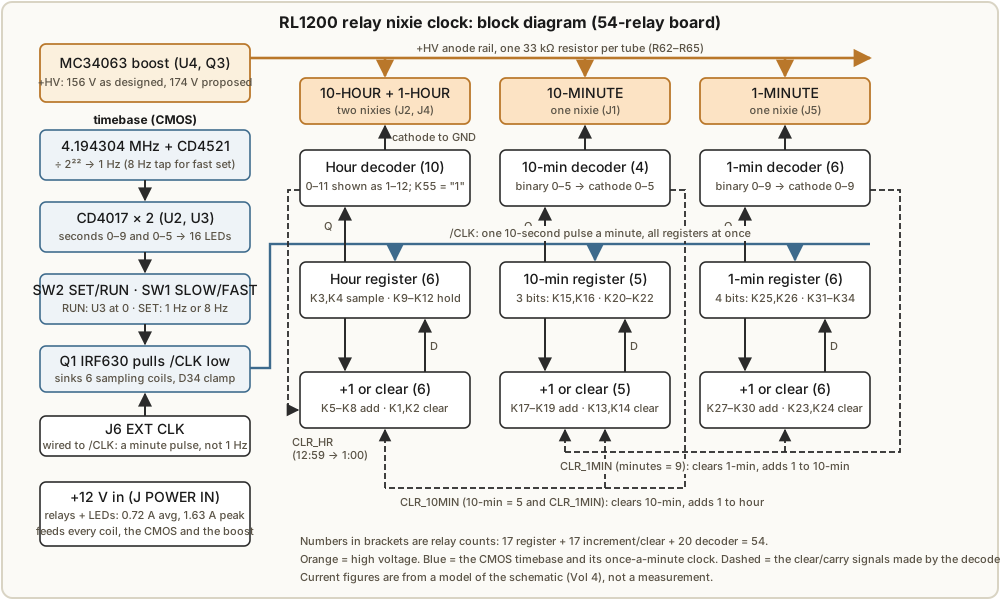
The board has five kinds of block:
Table 1 — The board has five kinds of block
| Block | Parts | Job |
|---|---|---|
| Timebase | Y1, U1 CD4521, U2 and U3 CD4017, SW1, SW2, Q1 | Make one long clock pulse per minute, and count and display the seconds on LEDs |
| Registers | 17 relays, 10 capacitors | Hold the hour (4 bits), 10-minute (3 bits) and 1-minute (4 bits) digits in binary |
| +1 and clear | 17 relays | Work out what each register should hold next minute |
| Decoders | 20 relays | Turn each binary number into “ground this one cathode” |
| Nixie HV supply | U4 MC34063, Q2, Q3, L1 | Boost 12 V to the anode voltage (Volume 2) |
Everything runs from a single +12 V input. The relays use CMOS-style logic levels: a 1 is +12 V and a 0 is ground, and every logic line is actively driven both ways.2 That choice is what lets one double-pole relay do the work of a half adder (§1.4), and it is the reason the design needs only 54 relays.
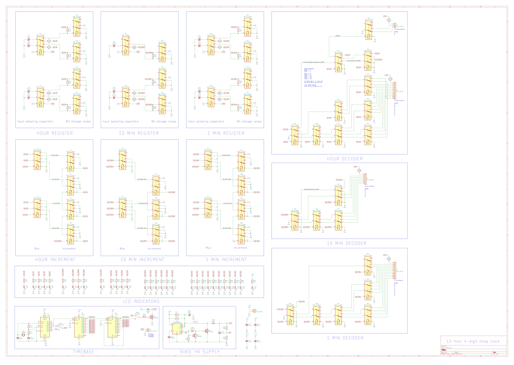
1.2 The timebase: silicon makes the minute
The relays are never asked to keep time. A small CMOS island does that, and hands the relays one clean pulse per minute.
The crystal and divider. Y1 is a 4.194304 MHz crystal, which is exactly 2²² Hz. U1, a CD4521 24-stage divider with its own oscillator, runs the crystal through R4 (2.2 MΩ bias), R7 (2.2 kΩ series) and C3/C9 (33 pF / 100 pF). Its Q22 output is therefore exactly 1 Hz, and its Q19 output is 8 Hz.3
The seconds. U2, a CD4017 decade counter, counts the 1 Hz tick 0 to 9 and lights one of ten LEDs. Its Q0 output rises each time it rolls over, which clocks U3, a second CD4017. U3’s Q6 output is wired back to its own reset, so it counts 0 to 5 and lights one of six LEDs. Together they show the seconds 00 to 59 on 16 LEDs, silently.
The minute pulse. U3’s Q0 output is high for the first ten seconds of every minute. In the RUN position of SW2, that signal drives the gate of Q1, an IRF630 MOSFET, which pulls the line called /CLK to ground. The bar means active low. /CLK goes low at :00, stays low for ten seconds, and releases at :10. D34 clamps the inductive kick from the relay coils on that line when Q1 turns off.
That ten-second pulse is long by any electronic standard. It has to be: the relays it drives need tens of milliseconds to operate, and the design needs the sampling relays held steady while everything downstream settles (§1.3).
Setting the time. SW2 in the SET position disconnects U3 and feeds Q1’s gate with a square wave instead. SW1 chooses SLOW (1 Hz, one minute per second) or FAST (8 Hz, eight minutes per second). Each cycle runs the whole register-update sequence exactly as a real minute pulse does.
External clock. J6, labelled EXT CLK, is wired straight to the /CLK line.3 The datasheet calls it an “active low external 1Hz reference”,1 but on the schematic it sits on the minute-clock line itself, so anything that pulls it low advances the clock one minute. Treat it as a once-a-minute input. A 1 Hz signal there would run the clock sixty times fast. Volume 4 has the details.
1.3 The register: a relay flip-flop that samples with a capacitor
Each register bit is a master–slave flip-flop built from relays and a capacitor. The 1-minute register has four bits; each pair of bits shares one double-pole sampling relay (K25 and K26), and each bit has its own storage relay (K31–K34) and its own 470 µF sampling capacitor (C1, C2, C14, C15).
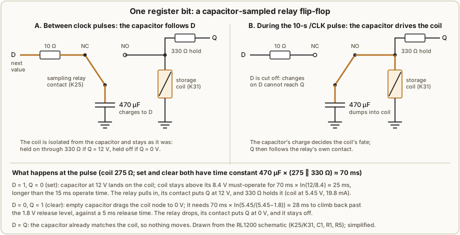
The storage relay holds itself. One pole of the storage relay is the bit’s output, Q: energised, it connects Q to +12 V; released, it connects Q to ground. A 330 Ω “holding resistor” runs from Q back to the relay’s own coil.13 If the relay is on, Q is +12 V, which keeps the coil energised through 330 Ω. If the relay is off, Q is ground, which keeps it off. Either state is stable indefinitely: one bit of memory.
Holding through 330 Ω also saves power. The coil is 275 Ω,4 so a held relay sees
V_coil = 12 V × 275 / (275 + 330) = 5.45 V
I_hold = 12 V / 605 Ω             = 19.8 mA
That is well above the coil’s must-release level (15% of 12 V, 1.8 V)4 but about half the 43.6 mA a fully driven coil draws.
The capacitor samples. Between pulses, the sampling relay is released. Its normally-closed contact connects the 470 µF capacitor to the bit’s D input (the value the bit should take next minute) through a 10 Ω resistor, which the datasheet calls the “inrush limiting resistor”. The capacitor charges to D, 0 V or 12 V, in a few milliseconds (10 Ω × 470 µF = 4.7 ms).
When /CLK goes low, the sampling relay pulls in. Its normally-open contact moves the capacitor off the D line and onto the storage relay’s coil. Four cases follow:
- D = 1, Q = 0 (set). The capacitor arrives at 12 V and drives the coil. With the coil and the 330 Ω (now returning to a grounded Q) in parallel, the time constant is 470 µF × (275 ∥ 330 Ω) ≈ 70 ms. The coil stays above its 70% must-operate voltage (8.4 V) for 70 ms × ln(12 / 8.4) ≈ 25 ms, longer than the relay’s 15 ms maximum operate time.4 The relay pulls in, Q goes to 12 V, and the 330 Ω takes over holding it.
- D = 0, Q = 1 (clear). The capacitor arrives empty and drags the coil to 0 V. It takes 70 ms × ln(5.45 / (5.45 − 1.8)) ≈ 28 ms to charge back past the 1.8 V release level, against a 5 ms maximum release time.4 The relay drops, Q goes to ground, and it stays off.
- D = Q. The capacitor already matches the coil, and nothing moves.
The 470 µF value is not arbitrary. It is what stretches those windows comfortably past the relay’s operate and release times. A capacitor that has dried out or lost capacity shrinks them, so a weak sampling capacitor is the first suspect for a bit that will not change (Volume 4).
Why this cannot race. While /CLK is low, the capacitor is disconnected from D. When the storage relays change Q, the +1 logic immediately starts working out a new D, but that new value cannot reach the bit being written, because the capacitor is not listening. The capacitor reconnects to D only when /CLK releases, ten seconds later, by which time everything has long since settled. The capacitor is the master and the relay is the slave. This is the same edge-triggered behaviour as a D-type flip-flop, made from parts that take milliseconds to move.
The designer explains why he went to this trouble.2 Most hobby clocks, including chip-based ones, use a ripple chain: the minutes counter rolls over and clocks the tens counter a moment later. With silicon that usually works. With relays, which are thousands of times slower, the timing hazards of a ripple design become real failures. So every register in the RL1200 is clocked by the same pulse, and every digit updates at once. This is a fully synchronous design.
1.4 The +1 stage: the relay coil as an XOR gate
Each digit has an incrementer that computes “Q plus one” continuously from the register’s outputs. It uses one DPDT relay per bit, and the trick is in the coil.
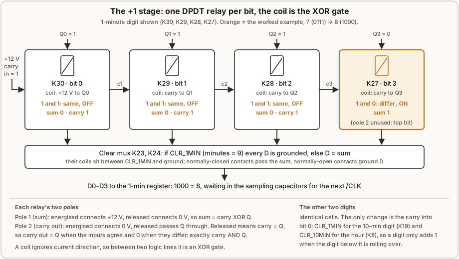
A relay coil does not care which way current flows through it. Wire it between two logic lines and it is energised when one is at 12 V and the other at 0 V, that is, when they differ. That is an exclusive-OR. In the incrementer, bit i’s coil is wired between the carry into that bit and Qᵢ:
- Pole 1 (sum). Energised connects +12 V, released connects ground. So sumᵢ = carryᵢ XOR Qᵢ.
- Pole 2 (carry out). Energised connects ground, released passes Qᵢ through. If the inputs agree, the carry out equals Qᵢ; if they differ, it is 0. That is exactly carryᵢ AND Qᵢ.
One relay is a complete half adder. For the 1-minute digit the carry into bit 0 is tied to +12 V, so the stage always adds one. In Figure 1.4, 0111 (7) produces sum 1000 (8). The top bit’s relay (K27) has no carry out, so its second pole is unused.
The 10-minute and hour incrementers are the same circuit with one change: the carry into bit 0 is not +12 V but the clear signal of the digit below (CLR_1MIN for the 10-minute digit at K19, CLR_10MIN for the hour at K8). When the lower digit is not rolling over, that carry is 0, the stage adds zero, and the digit stays where it is. The clear signal doubles as the enable.
1.5 The clear multiplexer and the rollover signals
Counting up is not enough: the minutes must go 9 → 0, the tens of minutes 5 → 0, and the hours 12 → 1. Each digit has two clear relays (K23/K24, K13/K14, K1/K2) between the incrementer and the register’s D inputs. Their coils sit between that digit’s clear signal and ground. Released, they pass the sum through; energised, they ground every D line, so the register loads 0 at the next pulse.
The three clear signals are made by spare poles on the decoder relays (§1.6):
Table 2 — The three clear signals are made by spare poles on the decoder relays (§1.6)
| Signal | Condition | Made by | Effect at the next pulse |
|---|---|---|---|
| CLR_1MIN | 1-min = 9 (Q3 · Q0) | K37 pole 1 | 1-min → 0, 10-min + 1 |
| CLR_10MIN | 10-min = 5 (Q2 · Q0) and CLR_1MIN | K36, K44 | 10-min → 0, hour + 1 |
| CLR_HR | hour code = 11 (Q3 · Q1 · Q0) and CLR_10MIN | K48, K41, K35 | hour → 0 |
Each condition only checks the bits that matter. In a decade counter, 9 is the only value from 0 to 9 with both Q3 and Q0 set, and 5 is the only value from 0 to 5 with Q2 and Q0 set, so two-bit tests are enough. The AND gates are built the same way as the carry poles: a chain of normally-open contacts, each passing the signal on only if its bit is 1.
1.6 The decoders: relay trees that ground one cathode
A nixie lights the digit whose cathode is pulled toward ground while the anode sits at high voltage through a current-limiting resistor (33 kΩ, one per tube: R62–R65). Each decoder is a binary tree of relay contacts that connects ground to exactly one of the tube’s cathodes.
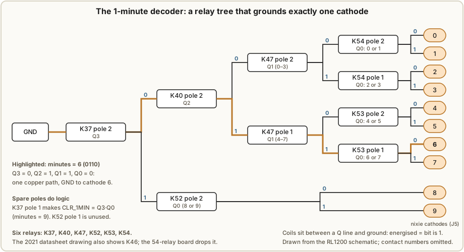
Each decoder relay’s coil sits between one Q line and ground, so it is energised when that bit is 1. In the 1-minute decoder, ground enters at K37 (bit 3). If bit 3 is 1, the value is 8 or 9 and K52 (bit 0) picks between them. If bit 3 is 0, K40 (bit 2), K47 (bit 1) and then K54 or K53 (bit 0) narrow it down to one of 0 to 7. One copper path is ever closed, so one cathode is ever lit.
The 1-minute decoder uses six relays. The 2021 datasheet’s placement drawing shows a seventh position, K46, which the designer later found unnecessary: “The newer revision of the board only requires 54 relays as a relay in the 1 min decoder was not necessary.”2 My board is the newer revision (Volume 3, Figure 3.2). The 10-minute decoder is the same idea for three bits and six cathodes, with four relays (K36, K39, K44, K45).
The hour decoder is the clever one. The hour register holds a code from 0 to 11, and the decoder displays it as 1 to 12, the conventional clock face, as labelled on the schematic:3
Table 3 — 1.6 The decoders: relay trees that ground one cathode
| Code | 0000 | 0001 | … | 0111 | 1000 | 1001 | 1010 | 1011 |
|---|---|---|---|---|---|---|---|---|
| Shows | 01 | 02 | … | 08 | 09 | 10 | 11 | 12 |
The offset is built into the wiring of the 1-hour tree (K35, K38, K42, K43, K49, K50, K51). The 10-hour tube gets its own relay, K55, driven by a signal called 10HOUR = Q3 · (Q1 + Q0), which is true for codes 9, 10 and 11, the hours 10, 11 and 12. Ten relays in all.
K55 grounds the 10-hour tube’s “1” cathode when 10HOUR is true and its “0” cathode when it is false, so as drawn the clock shows a leading zero, 09:41 rather than 9:41. The “02:46” visible in the designer’s own video2 is consistent with that. Blanking the zero takes one wire not being connected, which Volume 3 covers.
1.7 One minute, start to finish
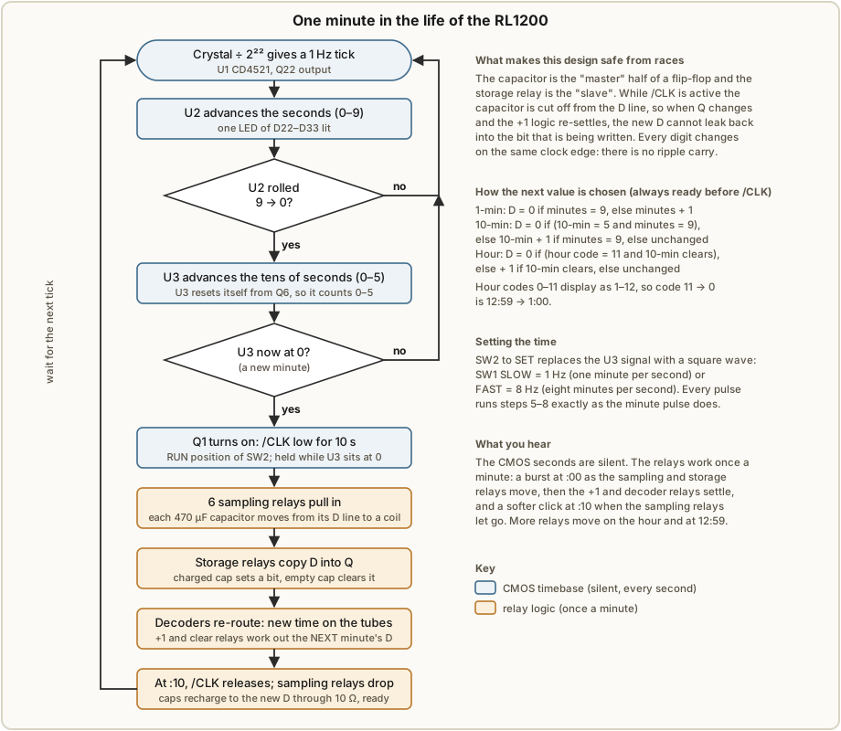
Putting the pieces together, here is what happens around the top of a minute, using the 1-minute digit going from 7 to 8:
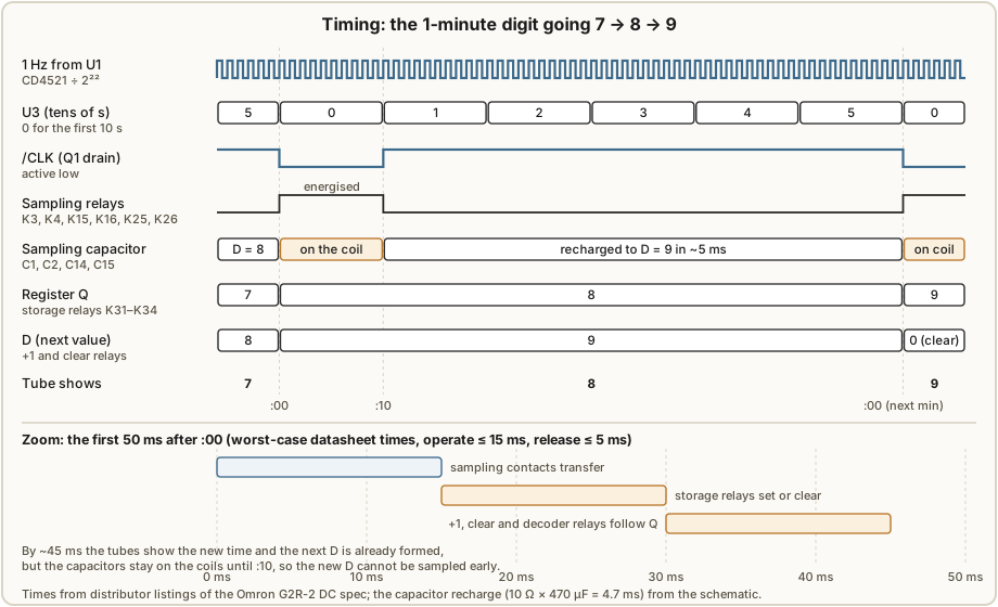
- Before :00. The register holds 0111 (7); the tube shows 7. The +1 stage has computed 1000 (8), and the sampling capacitors have charged to it.
- At :00. U3 returns to 0, Q1 pulls /CLK low, and all six sampling relays pull in within 15 ms.
- Within ~30 ms. Each capacitor drives its storage coil. Bit 3 sets; bits 0, 1 and 2 clear. Q is now 1000.
- Within ~45 ms. The decoder relays follow the new Q and the tube shows 8. The +1 relays follow too, and D becomes 1001 (9). The capacitors are still on the coils, so they cannot pick that up yet.
- At :10. U3 moves to 1, /CLK releases, and the sampling relays drop. The capacitors reconnect to D and recharge to 1001 within a few milliseconds, ready for the next minute.
At 12:59 every digit moves at once. CLR_1MIN, CLR_10MIN and CLR_HR are all true, the three clear multiplexers ground every D line, and at the pulse all eleven register bits load 0 together: 01:00. The logic model in Volume 4 steps through all 720 minutes of a twelve-hour cycle this way and confirms the sequence closes correctly.
1.8 What you hear, and what you see
The seconds are silent: two CMOS counters and a row of LEDs. The relays work once a minute, as a short burst at :00 (sampling relays, then storage relays, then the +1 and decoder relays catching up) and a softer click at :10 when the sampling relays let go. Ordinary minutes move a handful of relays. The top of each hour moves many more, and 12:59 → 1:00 moves the most.
Besides the four tubes and the 16 seconds LEDs, the board carries an LED on every register bit (D2, D4, D6, D8 for the hour; D5, D7, D9 for the 10-minute digit; D11–D14 for the 1-minute digit; each through 10 kΩ), so the binary value in each register is visible directly. On a clock built to show its own logic, that is the point.
1.9 References (Vol 1)
Footnotes
-
Catahoula Technologies, RL1200 – 4-digit 12-hour nixie clock datasheet (bill of materials, placement drawing, ports), 2021-08-09. Held in this clock’s
02-inputs/Designer - Catahoula RL1200/RL1200_ds.pdf. ↩ ↩2 ↩3 -
Jon Stanley, “Relay Logic Projects”, electronixandmore.com, https://www.electronixandmore.com/projects/relaylogic/index.html (page saved 2024-05-26 as
Relay Logic Projects.pdf; live page checked 2026-10-28). ↩ ↩2 ↩3 ↩4 ↩5 -
Catahoula Technologies, 12-hour 4-digit relay clock schematic (KiCad, sheet 1/1), 2021-08-10. Held as
RL1200_sch.pdfalongside the datasheet. ↩ ↩2 ↩3 ↩4 -
Omron G2R-2 12 VDC coil and timing data as listed by distributors: coil resistance 275 Ω, rated current 43.6 mA, must-operate 70% maximum, must-release 15% minimum (Bürklin, https://buerklin.com/en/p/omron/industrial-relays/g2r-2-12vdc/29G8682); operate 15 ms maximum, release 5 ms maximum (LCSC, https://www.lcsc.com/product-detail/C14539.html, DC24 variant). Confirm against Omron’s own datasheet before relying on a margin. ↩ ↩2 ↩3 ↩4
Comments (0)