Nixie Transistor Clock · Volume 3
Building It
My version 5 board, the parts list checked against the schematic, the parts that are now obsolete, the manual's build order, and the build log
This volume is the build: the board I have, the parts list checked against the schematic and the manual, the parts that are no longer made, the order the manual builds it in, and the build log.
3.1 My board
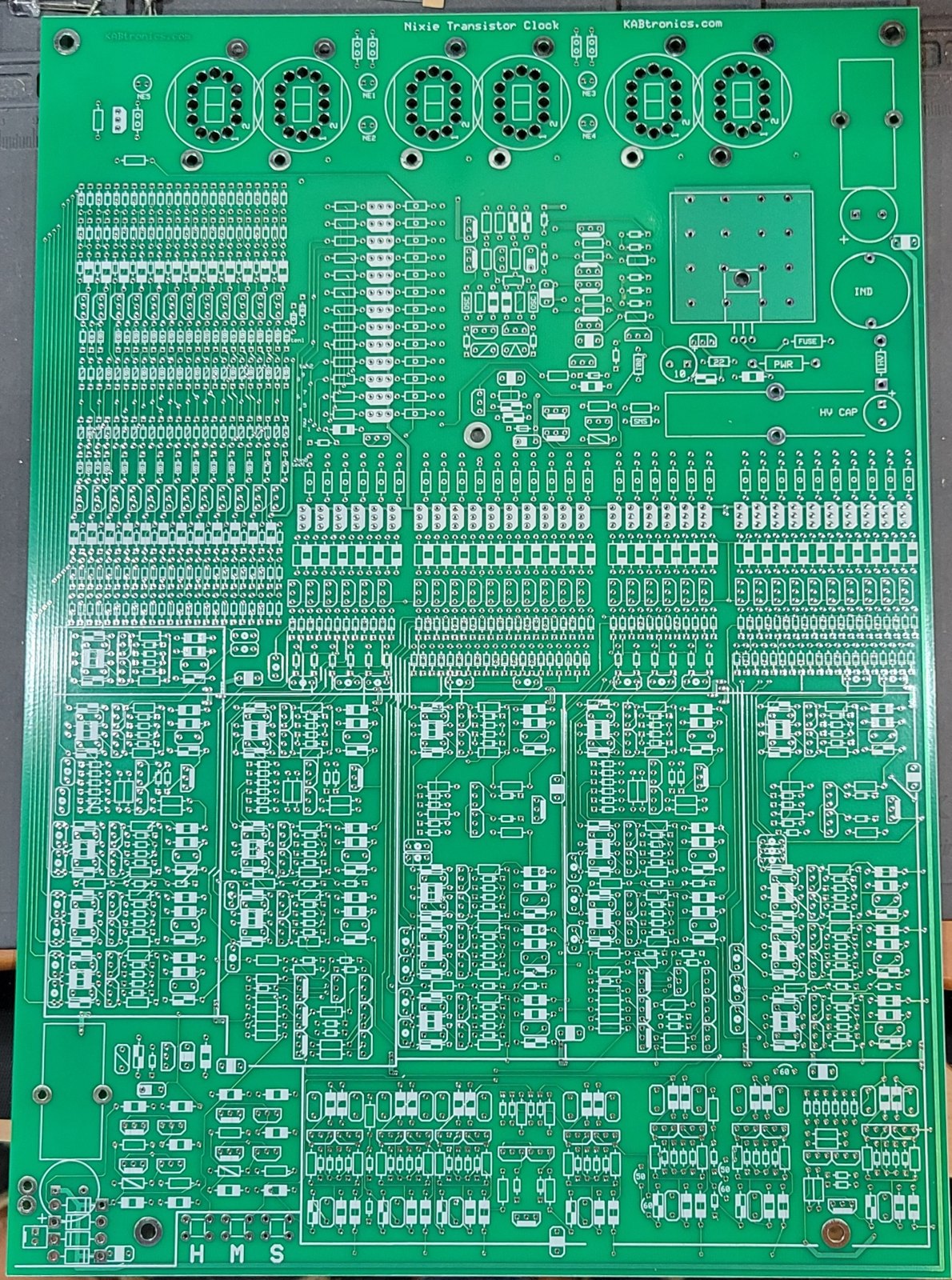
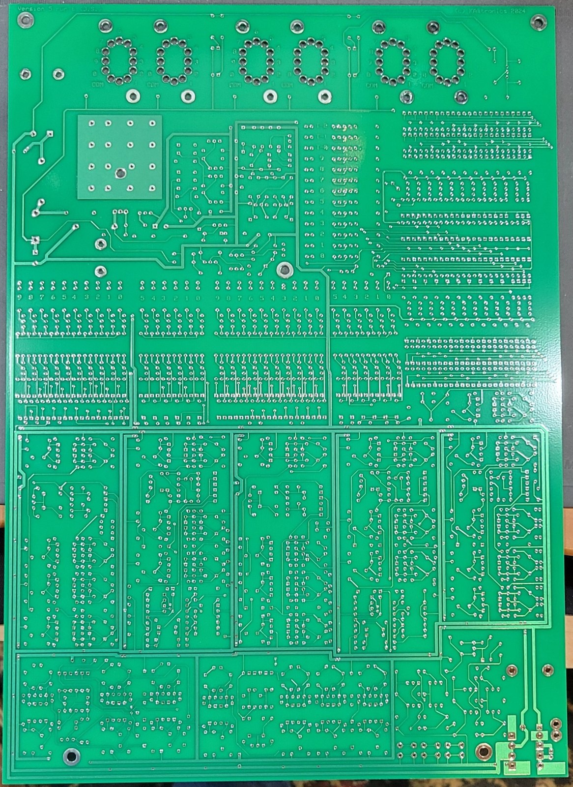
My board is PCB version 5, which is the version the current manual (document 1.7, 2016) is written for. The “2024” on the solder side is a later production run of the same version-5 design. That means:
- The manual matches the board. Where the silkscreen and the schematic disagree, the manual says “the silk screen symbols take precedence over the schematic”.1
- The published mods are already built in or do not apply. Mod 1 (a missing through-hole) is for version 3 boards. Mod 3 (the zener that makes hourly shut-off work per hour rather than all-or-nothing) applies to “PCB version 4 and earlier”, and the version 5 BOM already includes its zener. Mod 2, a potentiometer to adjust the HV and so the brightness, is marked “older version only” on the site; it is an idea, not a needed change.2
3.1.1 Where the parts go
The board has no reference designators. Its silkscreen shows each part’s type and value with a symbol (the manual’s legend, p. 86): resistor values by fill pattern, diodes by markings, and transistors by outline, with the high-voltage transistors drawn white-filled.1 So the board is stuffed by symbol and by section, not by designator. The manual divides it into 17 numbered sections, built in order.1
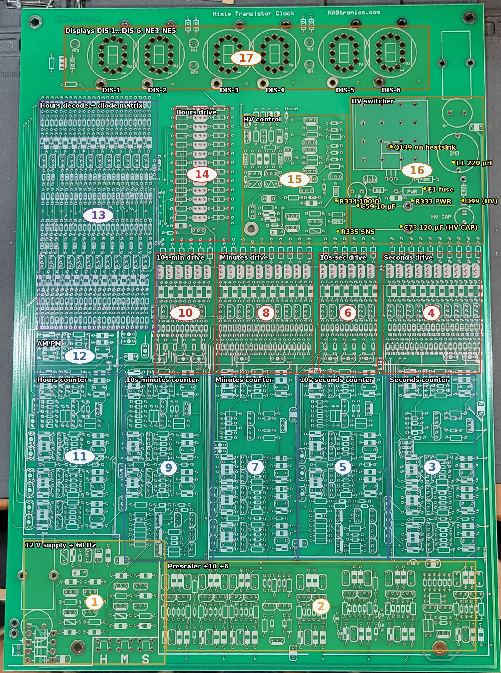
The 46 high-voltage driver transistors (the STX13003G, or its replacement, Volume 5) sit in three places, each on a white-filled outline:
- Sections 10, 8, 6 and 4: one row across the middle of the board, in four groups of 6, 10, 6 and 10, for the tens-of-minutes, minutes, tens-of-seconds and seconds tubes. Within each group the digits run 0 at the left to 5 or 9 at the right.
- Section 14: a column of 13 beside the hours decode, for the 10-hour digits 2, 1, 0 (top) and the hour digits 9 down to 0.
- Next to NE5 (top left): Q129, which drives the AM/PM neon.
The colon neons NE1–NE4 have no transistor; each is fed from the HV through its own 220 kΩ resistor and is always lit. The BOM’s 50 drivers therefore include 4 spares.
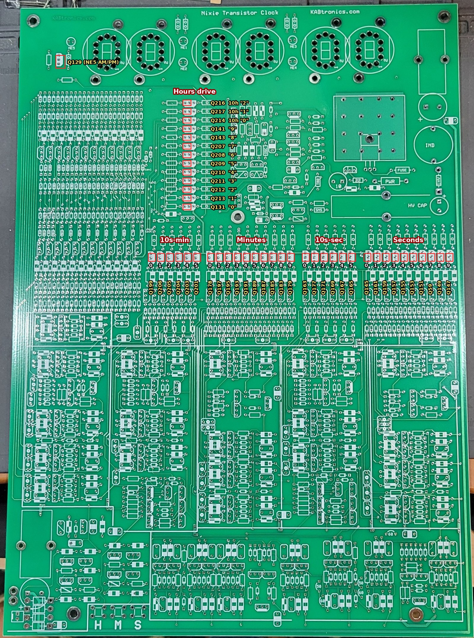
Table 1 — Where the parts go
| Tube | 0 | 1 | 2 | 3 | 4 | 5 | 6 | 7 | 8 | 9 |
|---|---|---|---|---|---|---|---|---|---|---|
| DIS-1, tens of hours | Q214 | Q217 | Q216 | |||||||
| DIS-2, hours | Q131 | Q213 | Q212 | Q211 | Q210 | Q209 | Q208 | Q207 | Q143 | Q141 |
| DIS-3, tens of minutes | Q199 | Q206 | Q205 | Q204 | Q203 | Q201 | ||||
| DIS-4, minutes | Q178 | Q197 | Q195 | Q193 | Q191 | Q189 | Q187 | Q185 | Q183 | Q179 |
| DIS-5, tens of seconds | Q163 | Q177 | Q171 | Q169 | Q167 | Q165 | ||||
| DIS-6, seconds | Q145 | Q161 | Q159 | Q157 | Q155 | Q153 | Q151 | Q59 | Q149 | Q147 |
How this was worked out, and how to confirm it: the designators come from the schematic’s tube sheets, read from the scanned pages; the board positions come from the digit labels printed beside each tube’s wiring holes on the solder side, mirrored to the component side. Each driver’s 22 kΩ cathode resistor runs to the wiring hole for its digit, so a continuity check from any driver position to the numbered hole above it confirms the digit before anything is soldered. The remaining ~1,200 parts are placed by the silkscreen symbols, section by section, as the manual’s build steps describe; giving every one a designator would mean tracing the whole board’s copper, and the board is not designed to be built that way.
In 24-hour mode the AM/PM lamp has no job. NE5, Q129 and its resistors can be left off, or fitted as a decoration.
3.2 The parts list, checked
The manual’s parts list (BOM updated 2015) against the schematic and build text. The kit supplies everything, so these notes matter most if you are sourcing parts yourself or checking what came in the box.
Table 2 — 3.2 The parts list, checked
| Item | BOM says | Check | Note |
|---|---|---|---|
| Transistors, NPN | 150 × 2N3904 | ✓ | The flip-flops, gates and decoders |
| Transistors, PNP | 30 × 2N3906 | ✓ | |
| HV cathode drivers | 50 × STX13003G (400 V, 1 A) | ⚠ obsolete | 45 cathodes + 5 neons; see §3.3 |
| Power switch Q139 | ”Transistor, NPN Power, TO-220” | ⚠ unspecified | A Darlington rated ≥ 300 V: MJE5742 (400 V, 8 A) is a safe choice (Volume 2, finding 7) |
| Q69 | 1 × MPSA56 | ✓ | |
| Signal diodes | 500 × 1N4148 | ✓ | The kit page counts 518 diodes in all; the 1N4148s are the bulk |
| Bridge rectifier | 4 × 1N5818 | ⚠ schematic shows 1N4002 | Use the BOM’s 1N5818 Schottkys (lower drop, less heat); 30 V reverse rating is enough here |
| HV diode D99 | ”Diode, 3A, 400V” | ✓ | MR854 on the schematic |
| Zeners | 2 × 4.7 V 0.5 W | ✓ | One is the HV reference, one is the hourly shut-off zener (Mod 3, built in) |
| C1, C72 | 2 × 6,800 µF | ⚠ no voltage given | 25 V minimum if sourcing; the rail reaches about 18 V unloaded |
| C73, HV reservoir | ”Capacitor, 120uF” | ⚠ no voltage given | 250 V minimum, 105 °C, if sourcing; it is the long electrolytic, held with a tie wrap |
| Tantalum | 1 × 10 µF 16 V | ✓ | C59, on the “+12 V” rail; 16 V is close to an 18 V unloaded rail, so a 25 V part is the safer substitute |
| Oscillator capacitors | 2 × “470” ceramic | ✓ | The PCB marks one 470 pF and one 0.001 µF; swap to tune the oscillator to about 22 kHz1 |
| Ceramics | 90 × 220 pF, 13 × 0.1 µF, 3 × 0.01 µF, 2 × 0.001 µF | ✓ | The 220 pF are the flip-flop speed-up and trigger capacitors |
| Inductor | 1 × 220 µH toroid | ✓ 2 A rated | See Volume 2, findings 5–6 |
| Resistors | 180 × 10 k, 180 × 100 k, 75 × 1 k, 50 × 22 k, 5 × 220 k, 3 × 1 M, 2 × 22 Ω, and singles | ✓ | 45 of the 22 kΩ are the cathode resistors |
| SNS set | 348 k, 357 k, 390 k | ✓ | Choose by measurement (Volume 2, §2.2); the schematic’s “380K” is superseded |
| PWR resistor | 1 × 0.47 Ω | ⚠ schematic shows 0.5 Ω | Use 0.47 Ω |
| Fuse | ”Fuse, 3A, Fast, pico” | ⚠ schematic shows 2 A | Use 3 A |
| Tubes and sockets | 6 × IN-12A, 6 × IN-12A sockets | ✓ | Floating-pin sockets, wired by hookup wire (§3.5) |
| Neon lamps | 5 | ✓ | About 70 V, 0.5 mA |
| LEDs | 16 × red 3 mm | ✓ | For checking the counters during the build |
| PCB | ”PCB, Nixie Version 3” | ⚠ stale line | The BOM line was never updated; the board is version 5 |
| Transformer | 12 VAC wall adapter (US mains) | ✓ | About 1.2 A in use; a 2 A unit gives headroom (Volume 2, §2.6) |
3.3 Obsolete parts
The complete sourcing list, with every original part, its replacement and the reason, is Volume 5. This section explains the two parts that need the most care.
Two parts need care if you are not using the ones from a kit.
STX13003G cathode drivers (50 needed). STMicroelectronics’ STX13003G is listed as obsolete by distributors.3 Each driver only has to switch about 1–2 mA and stand off the HV when its digit is dark, so the classic nixie driver MPSA42 (300 V, TO-92) is the usual substitute. Check the pinout before buying 50: TO-92 transistors do not all share one lead order. Compare the MPSA42’s datasheet (emitter, base, collector) with the transistor outline and the E/B/C or flat-side marking on the board, or with an STX13003G from a kit. If they differ, the leads can be crossed, but it is better to know before soldering 50 of them.
Q139, the power Darlington. The schematic calls it only “8AMP” and the BOM “NPN Power, TO-220”. It switches the inductor and sees the full HV plus switching overshoot when it turns off, so it must be a high-voltage Darlington: the MJE5742 (400 V, 8 A, TO-220) fits. A general-purpose TO-220 Darlington such as a TIP120 (60 V) would fail at once. If the kit supplied a part, read its marking and check its voltage rating.
3.4 Build order
The manual builds the clock in tested stages, about 20 hours of work in all.1 Its order:
- 12 V supply and the 60 Hz extractor. Check about 12 V on the large electrolytic and a 60 Hz square wave at the prescaler input.
- Seconds counter, decode and drive. The 16 LEDs are used to watch the counters work before any tube is fitted.
- The rest of the counters.
- Hours decode and drive, including the 12- or 24-hour diodes.
- High-voltage supply, last, after everything else works, with the staged bring-up in Volume 2, §2.4.
- Nixie and neon displays, then final assembly and test.
Habits that matter on a board of 2,917 joints, from the manual’s troubleshooting list in order of likelihood: wrong part loaded, part loaded backwards, a bad joint or solder bridge, a clipped lead stuck to the back of the board, or the board resting on something conductive. Keep the bench clear and look at the back of the board often.
3.5 Wiring the tubes
The IN-12A sockets are floating-pin sockets with solder lugs, and they are not soldered to the PCB: the lugs must stay free so the glass is not stressed. Each tube is wired with hookup wire from its socket lugs to a row of numbered holes next to it, one per digit, plus a COM lug that goes to the HV hole beside it.1 Bundle the wires neatly, and clip off the wire ends on the front of the board so nothing can bend over and touch.
When fitting the tubes, pin 1 is white inside the glass, and goes to the lower-right position on the board. Push them in gently; the glass cracks if the pins are stressed.1
Every cathode lead carries up to the HV whenever its digit is dark, not just COM.
3.6 Safety during the build
- Build the HV supply last, as the manual says.
- After the HV is working, wait and measure before touching anything: the 120 µF capacitor holds 1.6–1.9 J and takes about a minute and a half to bleed down (Volume 2, §2.3), longer than any other clock in this hub.
- Work one-handed with power applied.
- Dark tubes do not mean a safe board, especially during shut-off hours.
- The finished clock belongs “up high, behind glass”, in the manual’s words.
3.7 Buy instead of build
KABtronics sells the kit (board, all parts, tubes, sockets, transformer and printed manual) through the order page linked from tube-clock.com.4 Price and availability are not recorded here; check the order page.
3.8 Build log
-
2026-10-29. Board in hand: a bare version 5 PCB, front and back photographed (Figures 3.1 and 3.2). Manual, mod sheets and site photos downloaded; the schematic and BOM reviewed (this volume and Volume 2).
-
2026-10-29 (later). Decided: I have the bare board only, so every part is mine to source, including the obsolete and unspecified ones in §3.3. The clock will run 24-hour with leading zeros (00:00 to 23:59, the 10-hour tube showing 0 for hours 00–09, set by the diodes the silkscreen marks for 24-hour), and I am fitting the 150 kΩ bleeder across C73 (Volume 2, §2.5).
3.9 References (Vol 3)
Footnotes
-
Keith Bayern, KABtronics, Nixie-Transistor Clock Assembly Manual, document 1.7 for PCB version 5, 2016, https://tube-clock.com/neon_man.pdf: parts list, build order, high-voltage bring-up, Nixie and neon displays, final assembly, troubleshooting. ↩ ↩2 ↩3 ↩4 ↩5 ↩6 ↩7
-
KABtronics mod sheets, linked from https://tube-clock.com/index_002.htm:
v3mod1.pdf(version 3 boards),brightnessMod.pdf(marked “older version only”),24hour_mod_21.pdf(“Applies to KABtronics Nixie clock PCB version 4 and earlier”). Held in this clock’s02-inputs/Designer - KABtronics/. ↩ -
Distributor listings marking the STMicroelectronics STX13003G obsolete: ic-direct.com, https://ic-direct.com/product/stmicroelectronics/stx13003g/ and microchipusa.com, https://www.microchipusa.com/product/stmicroelectronics/single-bipolar-transistors/STX13003G (checked 2026-10-29). ↩
-
KABtronics, tube-clock.com, https://tube-clock.com/index.html. ↩
Comments (0)