Nixie Transistor Clock · Volume 1
How It Works
Theory of operation for the KABtronics Nixie Transistor Clock: no integrated circuits, a mains timebase, a ripple counter of discrete flip-flops, and six IN-12A tubes
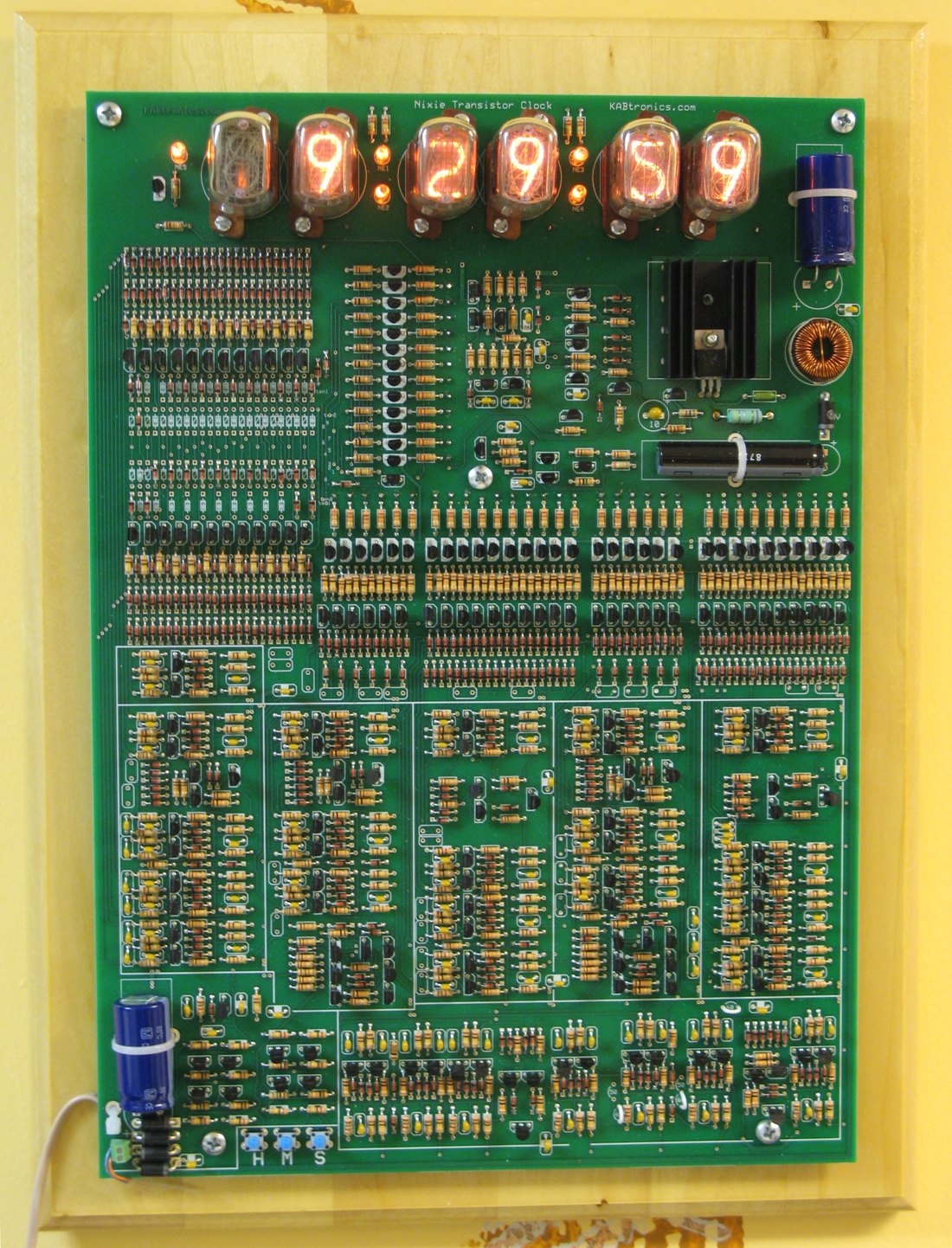
The Nixie Transistor Clock is a six-digit (HH:MM:SS) nixie clock with no integrated circuits at all. Every counter, gate, decoder and driver is built from discrete parts: the kit lists about 215 transistors, 518 diodes, 472 resistors and 101 capacitors on a 10 × 14 inch board, and the manual counts 2,917 solder joints.12 It is designed by Keith Bayern of KABtronics, the nixie sibling of the KABtronics Transistor Wall Clock that Nuts & Volts published in July 2009, which uses the same logic family with LED displays. Nuts & Volts returned to it in April 2012 with Bayern’s “Return to Transistor Land”, on designing this clock’s no-IC high-voltage supply.3
I have the bare version 5 board (Volume 3). This volume explains how the clock works. Volume 2 reviews its high-voltage supply, Volume 3 covers the build and the parts list, and Volume 4 covers running it.
The hub’s LED technology dive is anchored on the LED clock and explains its building blocks from the transistor up: the switch, diode gates, the bistable, the toggle flip-flop, decade counters, decoders and the mains timebase. The nixie clock uses the same circuits, so this volume describes them briefly and spends its time on what is different: the decoding onto ten-cathode tubes, the high-voltage drivers and the boost converter.
1.1 The clock at a glance
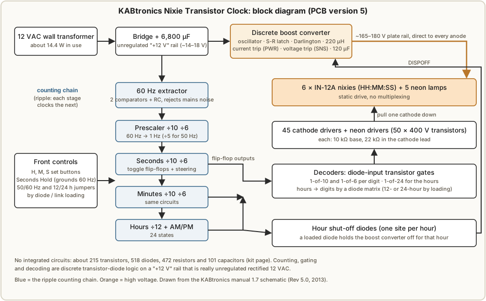
Table 1 — 1.1 The clock at a glance
| Block | Job | Schematic pages |
|---|---|---|
| Power supply and 60 Hz extractor | Rectify 12 VAC; make a clean 60 Hz square wave | 2 |
| High-voltage supply | Boost the rail to about 165–180 V for the tubes (Volume 2) | 3 |
| Prescaler | Divide 60 Hz by 10 and then 6, to 1 Hz | 4–5 |
| Seconds, minutes, hours counters | ÷10 ÷6, ÷10 ÷6, ÷12 with an AM/PM flip-flop | 6–11 |
| Decoders | One-of-ten, one-of-six and one-of-24 transistor gates | 12–21 |
| Display drivers | One 400 V transistor and 22 kΩ resistor per cathode | 13–23 |
The schematic sheets are numbered 1 to 23 within the manual’s own page numbering (pages 63–85 of the manual).2
1.2 Power and the 60 Hz timebase
The clock runs from a 12 VAC wall transformer. A diode bridge and a 6,800 µF capacitor (C1) make the logic supply, which the schematic calls “+12 V” but which is unregulated: the manual notes it is about 18 V with no load, and in use it sits somewhere around 14–17 V depending on the load and the mains.2 Discrete transistor logic tolerates that easily.
The clock keeps time by counting the mains frequency. One side of the bridge is compared with half the rail by a transistor comparator (Q1–Q4, with 1 MΩ hysteresis), giving a 60 Hz pulse train. Its falling edge discharges a capacitor (C5, 0.1 µF) through Q5; the capacitor recharges through 100 kΩ, and a second comparator (Q6–Q9) squares the result into the 60 Hz clock.
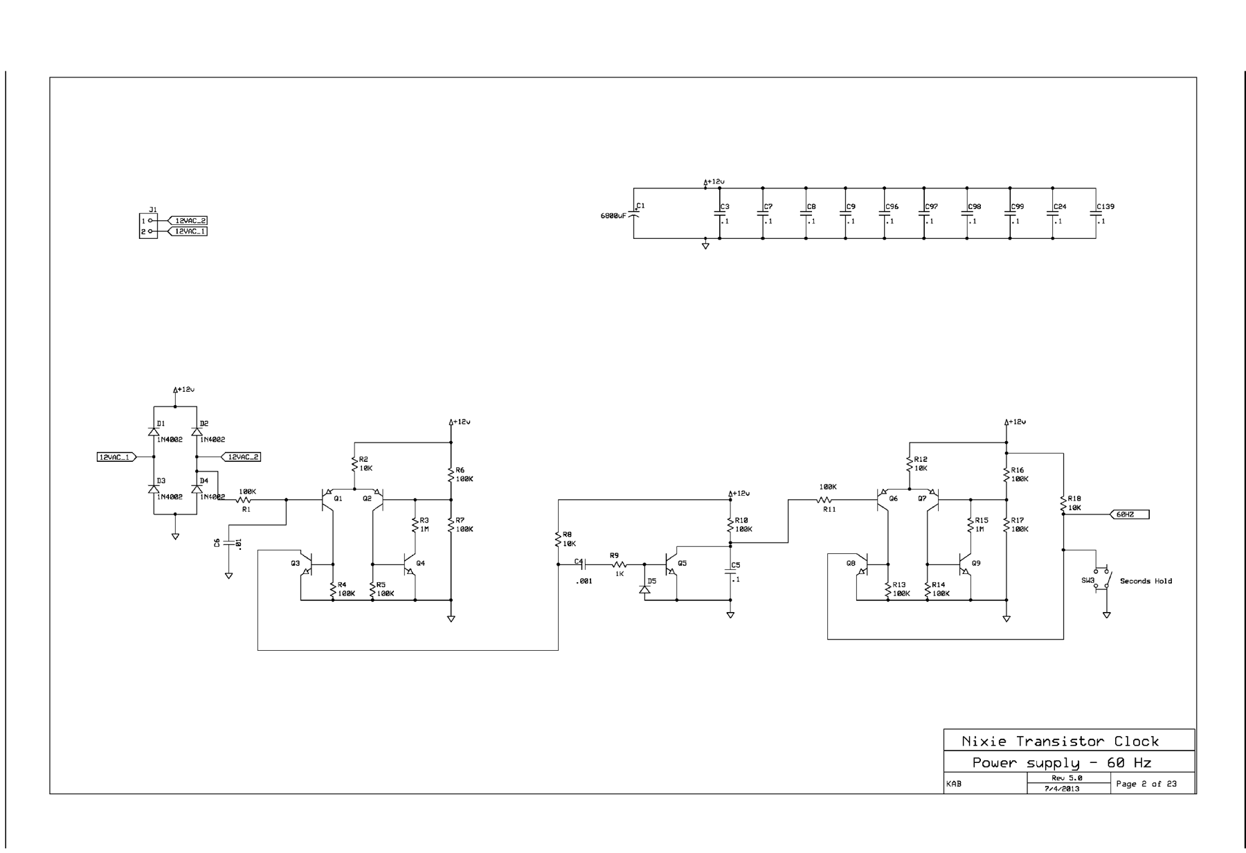
The detour through the capacitor is a noise filter. The capacitor charges just fast enough to trip the second comparator once per mains cycle. A burst of noise on the power line that triggers the first comparator early simply discharges the capacitor again before it has charged, so the clock misses a count rather than gaining one. The designer describes it as a brick-wall low-pass filter with a cutoff around 120 Hz.2 The hub’s LED dive covers this extractor in detail, including why mains time is accurate over the long run.
Seconds Hold (SW3) grounds the 60 Hz line, freezing the clock so it can be started on the second.
1.3 The counters: discrete flip-flops in a ripple chain
Every counter is built from toggle flip-flops, each a cross-coupled pair of 2N3904 transistors with 10 kΩ collector loads, 100 kΩ cross-coupling resistors and 220 pF speed-up capacitors. A diode-steered RC differentiator (220 pF into 100 kΩ) turns each falling edge at the input into a short pulse that flips it.2
A chain of four flip-flops counts to 16. To count to ten, the manual’s decade counter steers the clocks with gates made of diodes and transistors:
- Flip-flop 0 toggles on every input pulse.
- Flip-flop 1 is clocked by Q0 AND NOT-Q3, so the pulse that would take it to 1 at the count of 9 is masked.
- Flip-flop 2 is clocked directly by Q1.
- Flip-flop 3 is clocked by (Q2 AND NOT-Q3) OR (Q0 AND Q3): it follows Q2 for counts 0–7 and Q0 for counts 8 and 9.
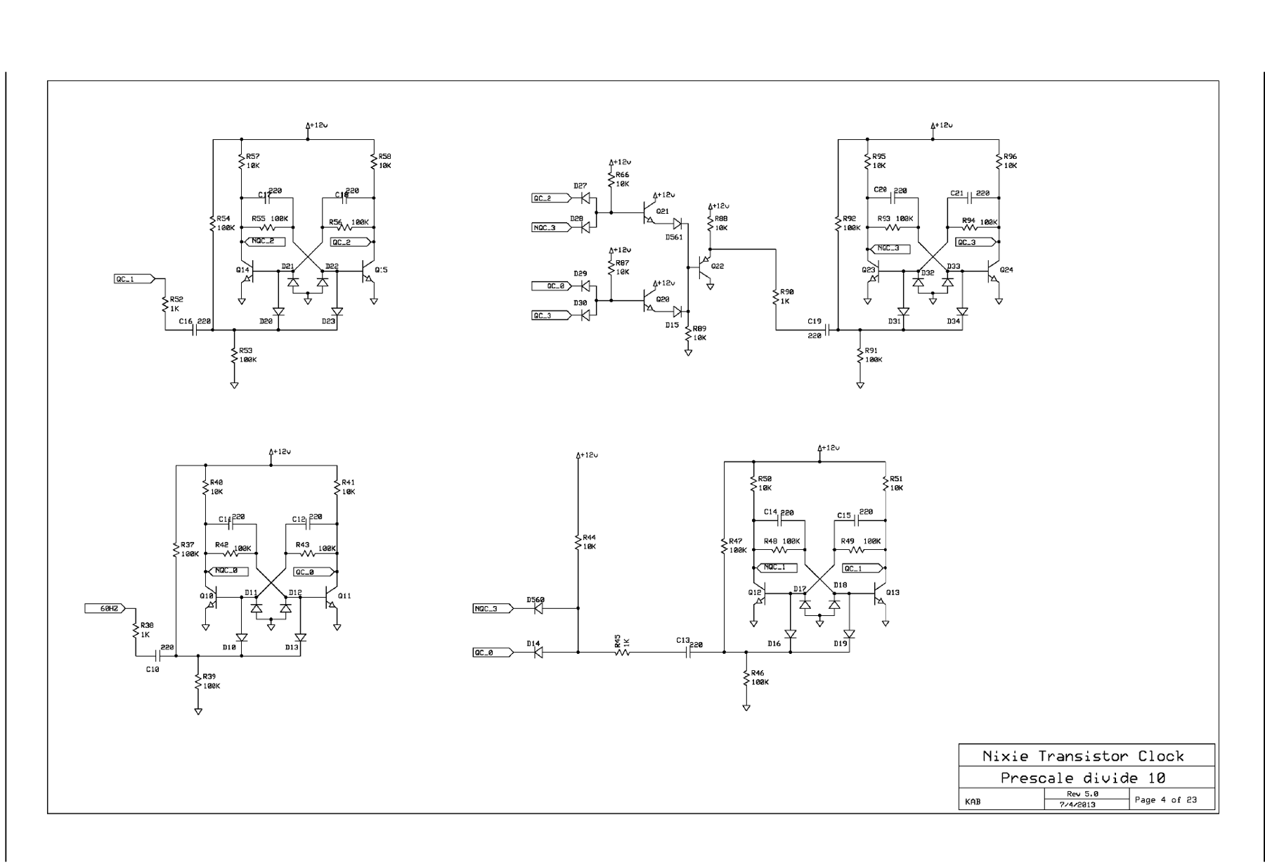
The divide-by-six stages use three flip-flops and a similar selector. The prescaler divides 60 Hz by 10 and then by 6 to make 1 Hz; the 50 Hz option changes that second stage to divide by five, set by jumpers.
This is a ripple counter: “This clock is a chain of dividers, each divider clocking the next divider.”2 The 1 Hz output clocks the seconds units; their rollover clocks the seconds tens; and so on up to the hours. Each stage changes a moment after the one below it. With transistor flip-flops switching in microseconds, the whole ripple settles long before anyone can see it, so the simple design works. It is the opposite choice from the relay clock in these same pages, whose designer made every digit update on one shared clock pulse precisely because relays are slow enough to turn ripple timing into real errors.
1.4 The hours: 24 states and a diode matrix
The hours counter counts 0 to 11 with a fifth flip-flop for AM/PM, 24 states in all. Rather than decode that into tens and units directly, the clock gives each of the 24 states its own one-of-24 decoder (Q101–Q123 for AM and their PM twins), and a diode matrix maps each hour onto the 1-hour and 10-hour cathode lines.2
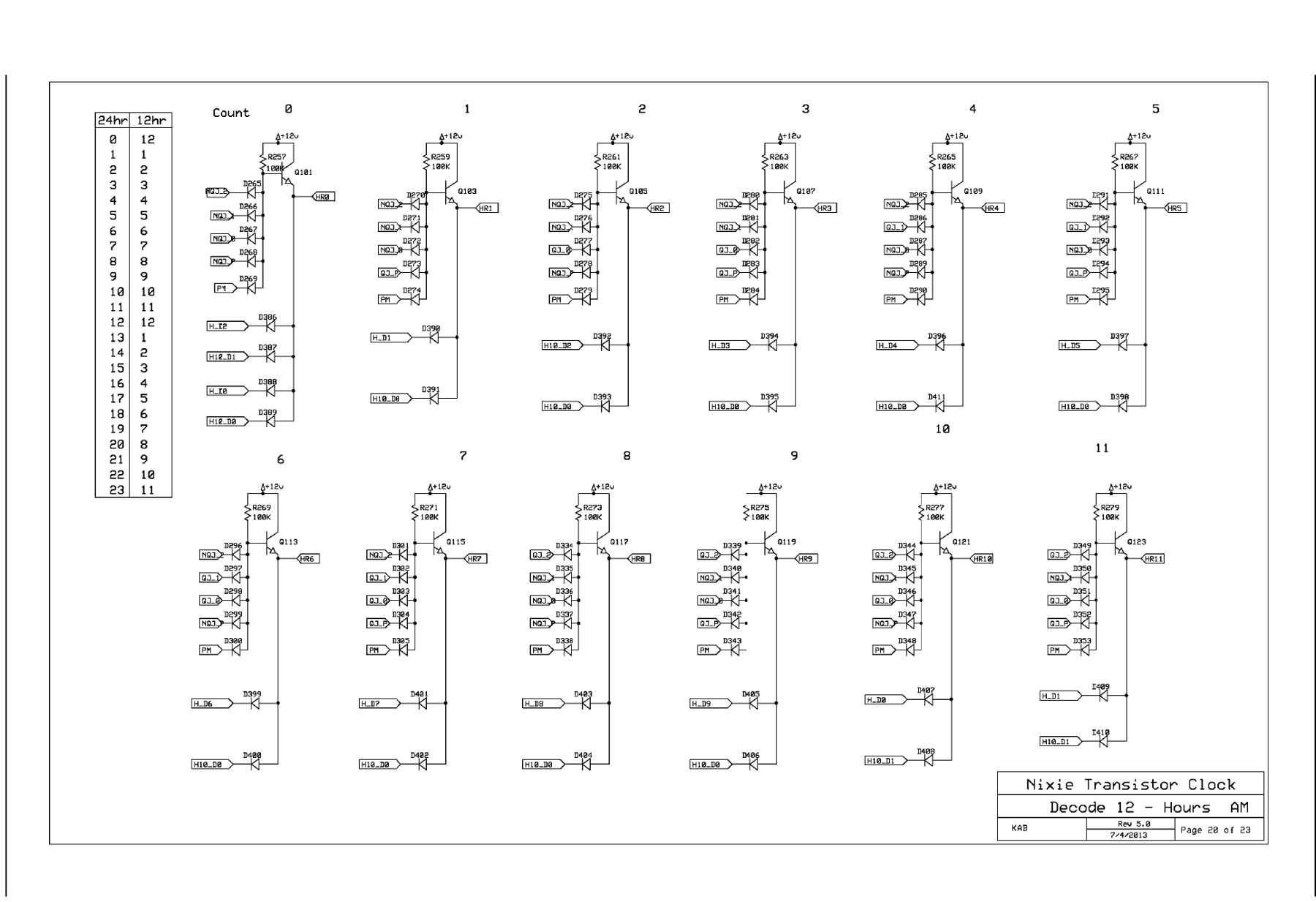
Because the mapping is made of diodes, 12-hour or 24-hour display is a choice of which diodes to load: count 0, for example, can light “12” or “00”. The board’s silkscreen marks the positions to load for each.2 The same trick provides the hour shut-off: one more diode site per hour connects that hour’s decoder to a line called DISPOFF, which holds the high-voltage supply off, so the tubes go dark for any hours chosen (overnight, say).
1.5 The decoders
The minutes and seconds use one-of-ten and one-of-six decoders. Each output is a transistor whose base is fed through four diodes from the counter’s flip-flop outputs and their inverses, so exactly one decoder output is active for each count.2 The manual’s troubleshooting section makes a point worth remembering: a fault in a decoder can load the flip-flops it reads and make the counter miscount, so a counter that skips states is not always a counter fault.
1.6 Driving the tubes
The display is six IN-12A nixies, end-view tubes with 18 mm digits, plus five neon lamps (four for the colons, and a fifth at the left end, NE5).2 The drive is static: every tube is lit all the time, with no multiplexing.
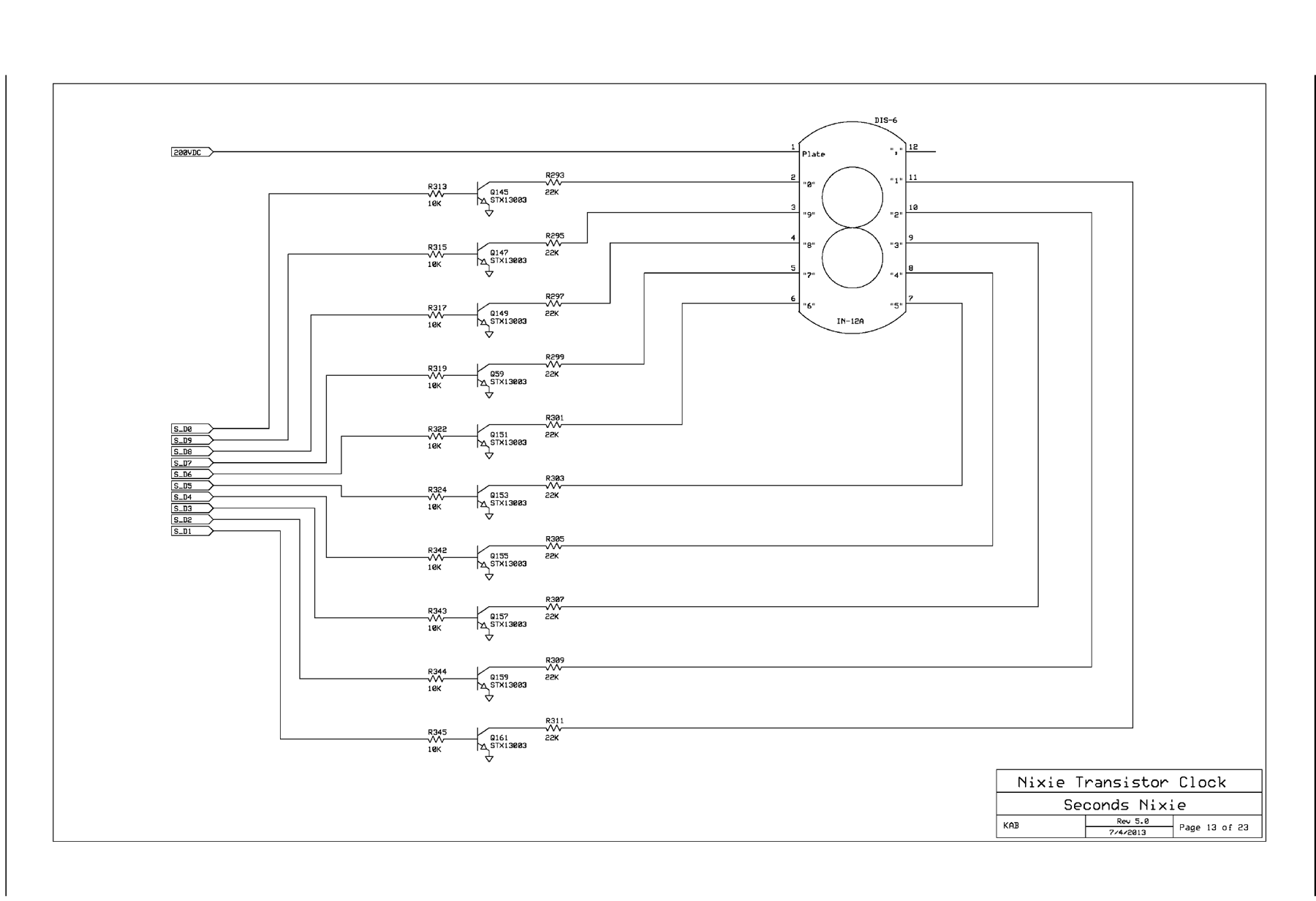
The wiring is the reverse of many nixie clocks. Each tube’s anode (plate) connects directly to the HV rail, with no anode resistor. Instead, each cathode has its own 22 kΩ resistor in series with an STX13003 transistor rated 400 V, whose base is driven through 10 kΩ by one decoder output.2 When a decoder line goes high, its transistor pulls that one cathode toward ground through the 22 kΩ, and the digit lights.
That makes 45 cathode resistors in all: 10 + 6 + 10 + 6 + 10 for the five full digits and 3 for the 10-hour tube (0, 1 and 2, enough for 24-hour time). The current through a lit digit is set by the HV voltage and that resistor:
I = (V_HV − V_maintain) / 22 kΩ        IN-12A maintains about 145 V
at 165 V:  (165 − 145) / 22 k ≈ 0.9 mA
at 180 V:  (180 − 145) / 22 k ≈ 1.6 mA
The IN-12A datasheet gives 2.5–3.5 mA as typical, so these tubes run gently; Volume 2 looks at why, and what to do if the digits look patchy.4
1.7 Setting the time
Three push buttons marked H, M and S set the time, feeding pulses into the counter chain through the time-setting logic beside the prescaler.2 Seconds Hold freezes the count, so the usual method is to set the hours and minutes, hold the seconds at the right moment, and release on the beat.
1.8 References (Vol 1)
Footnotes
-
KABtronics, “Nixie-Transistor Clock”, tube-clock.com, https://tube-clock.com/index.html and https://tube-clock.com/index_002.htm (kit contents, “no integrated circuits”, 1250+ parts; checked 2026-10-29). ↩
-
Keith Bayern, KABtronics, Nixie-Transistor Clock Assembly Manual, document 1.7 for PCB version 5, 8 October 2016 (87 pages: build order, theory of operation, circuit description, troubleshooting, schematic sheets 1–23 at Rev 5.0, 4 July 2013), https://tube-clock.com/neon_man.pdf. Held in this clock’s
02-inputs/Designer - KABtronics/and in the central Library. ↩ ↩2 ↩3 ↩4 ↩5 ↩6 ↩7 ↩8 ↩9 ↩10 ↩11 ↩12 -
Keith Bayern, “Return to Transistor Land,” Nuts & Volts, April 2012, p. 36, https://www.nutsvolts.com/magazine/article/april2012_Bayern; and “Transistor Clock,” July 2009, https://www.nutsvolts.com/magazine/article/transistor_clock. This clock is also listed among my Nuts & Volts builds. ↩
-
IN-12 nixie tube datasheet (English translation), central Library
in-12-nixie-tubes-datasheet-eng: typical plate voltage about 145 V, typical cathode current 2.5–3.5 mA. ↩
Comments (0)