Scope · Volume 11
Enclosure, Finishing & the Steampunk Treatment
Mounting the tube, taming the high voltage inside the box, and dressing it in brass
Everything in the previous ten volumes has lived on the bench — a bare board, a tube in a clamp, a high-voltage supply on a sheet of plywood with the probes still hanging off it. This volume is about the last twenty percent of the project that takes the longest: turning a working circuit into an object that can sit on a shelf, be handled by people who do not know what is inside it, and earn the second glance that a scope clock deserves. That last requirement is where the scope clock diverges from almost every other hobby-electronics build. A finished scope clock is a piece of furniture and a piece of test gear at the same time, and the most beloved examples — the brass-and-glass steampunk pieces that fill the community galleries — are deliberate homages to the 1920s-through-1950s instruments the CRT itself came from. The enclosure is therefore not an afterthought. It is the part of the build that the world actually sees, and it is the part that stands between a casual hand and a few hundred volts. Those two facts are in tension, and resolving them well is the whole craft of this volume.
11.1 Mechanical integration
Before any of the aesthetic decisions, the enclosure has a job: hold a fragile, high-voltage vacuum tube and one or more boards in a fixed relationship to each other and to the viewer, without stressing the glass, pinching a wire, or letting the anode lead touch anything it should not. The mechanical layout is also the thing that, once chosen, constrains everything decorative that follows — so it is worth getting the skeleton right before reaching for the brass polish.
11.1.1 Mounting the CRT — supporting the glass, not stressing it
A small electrostatic CRT is mechanically a glass cylinder with a heavy-ish faceplate at one end and a fragile pinched-glass neck with the base pins at the other. The cardinal rule is that the tube must be supported around its body (the wide cylindrical section), never hung from its neck and never clamped hard against its face. The neck glass and the seal where the pins enter are the weakest points; a tube that is allowed to swing on its base pins, or that is wedged so the faceplate takes a point load, will eventually crack — and a cracked CRT is an implosion hazard, not just a dead part (the vacuum and implosion mechanics are covered in Vol 2, and the implosion risk is reiterated in the safety brief, Vol 12).
Two mounting schemes dominate the community builds:
- A cradle or saddle — a curved support (often two laser-cut or 3-D-printed rings, or a folded-metal bracket lined with felt, cork, or silicone) that the tube body rests in, with a soft strap over the top. This spreads the load over a wide arc of glass and tolerates the tube’s taper. It is the gentlest method and the easiest to make adjustable for centering.
- Clips — sprung metal or printed clips that grip the body at two or three points. Faster to build, but every clip is a point load, so the contact faces must be lined with something compliant and the spring force kept modest.
Whatever holds the body, the neck wants a light second support — a soft grommet or a printed collar that locates the neck laterally without clamping it — so that handling shocks are not transmitted to the base pins or the internal gun structure. The base socket itself should float on its wire harness or sit in a compliant holder; it must not be the thing that carries the tube’s weight.
11.1.2 Mounting the boards
The controller board and the high-voltage / deflection board (one PCB on some designs, two on others — see the OSC4.4 and Dutchtronix layouts in Vols 7 and 8) mount on standoffs, not flat against a conductive panel. Metal standoffs are fine for the logic board if the panel is grounded, but the HV board wants insulating standoffs (nylon or PTFE) and generous air gaps to any metalwork, for the creepage reasons in § 11.2. Orient the boards so the tallest, hottest, and highest-voltage parts — the flyback or HV multiplier, the reservoir capacitors, the deflection-amp output transistors and their heatsinks — sit where convection can carry heat upward and out of a vent, and where their terminals face away from the touchable skin of the case.
Keep the analog deflection wiring short and routed away from the switching HV supply; a long unshielded run from a deflection amp to a deflection plate will pick up the supply’s switching hash and put ripple on the trace. This is an electrical concern that the mechanical layout decides, so it belongs here, in the skeleton stage.
11.1.3 The face bezel, the mask, and the viewing hood
The round screen of an electrostatic CRT is rarely the same diameter as the useful image, and the faceplate is often a slightly domed circle set into a square or rectangular front panel. Three layered parts solve the framing problem:
- The bezel — the ring or frame that mechanically retains the front of the tube and trims the hole in the front panel. On instrument-style builds this is a turned metal ring; on steampunk builds it is very often a salvaged brass porthole, a clock bezel, a camera lens ring, or a plumbing flange. The bezel must not clamp the faceplate hard; a soft gasket between bezel and glass both cushions the tube and hides the diameter mismatch.
- The mask — an opaque aperture behind the bezel that hides the unused rim of the phosphor and the internal structure, leaving a clean circular (or, charmingly, a rounded-rectangle “CRT” shaped) window. A matte-black mask also kills internal reflections and makes the trace look brighter by contrast.
- The viewing hood — an optional short shade or recessed tube around the screen. Because a vector trace is dim compared to a backlit modern display, anything that keeps ambient light off the phosphor dramatically improves perceived contrast. A hood is the cheapest contrast improvement available, and it reads as authentically instrument-like (radar scopes and lab CRTs wore them for exactly this reason).
The tube’s physical size dictates all three parts and a good deal of the overall proportions of the clock — choosing the tube is therefore partly an enclosure decision, which is why Vol 6 (CRT selection) and this volume are best read together.
11.1.4 Ventilation for the HV section
The heater, the HV supply, and the deflection-amp output devices all dissipate heat, and a sealed decorative box will cook them. Ventilation is therefore a requirement, not a nicety — but it competes directly with two other requirements: keeping fingers out, and keeping the high voltage in. The resolution is convection venting: low inlets and high outlets so warm air rises out on its own, sized and placed so that nothing conductive (a paperclip, a curious finger, a cat’s whisker) can be poked through a vent to reach a live node. Louvers, a perforated brass screen, or the gaps between decorative slats all work and all read as period-correct on a steampunk shell. If a fan is used, it should be a quiet low-RPM unit pulling through a filtered inlet, and its metal frame must be bonded to the chassis ground.
11.2 Safety-driven enclosure design
This is the recurring theme of the whole series and the non-negotiable constraint on
everything decorative in this volume: a scope clock enclosure is a high-voltage
enclosure first and a pretty box second. The deflection and supply voltages reach from
several hundred volts to a couple of kilovolts on the anode; the reservoir and supply
capacitors stay charged after the clock is unplugged; and a steampunk shell, by its
nature, is often built largely of conductive metal. Those facts drive the design. The
full safety discipline lives in Vol 12 and the hub-wide _shared/safety.md; what follows
is the enclosure-specific subset.
11.2.1 Grounded conductive case, or properly-insulated case — pick one and commit
There are two defensible enclosure philosophies, and the dangerous builds are the ones that drift between them:
- A grounded conductive case. Every piece of exposed metal the user can touch — the brass skin, the bezel, the bolt heads, the metal feet — is bonded together and connected to mains protective earth (the third pin). If an internal fault puts a live voltage onto the metalwork, the earth connection carries the fault current and trips the protective device instead of waiting for a hand to complete the circuit. This is the right answer for almost every metal-bodied steampunk build. The bonding must be real: a star-washer’d ring terminal to bare metal at each panel, with continuity measured, not assumed — decorative lacquer and patina are insulators.
- A fully-insulated (double-insulated) case. The user-touchable shell is non-conductive (wood, certain plastics, glass) and there is no reliance on earthing because nothing the user touches can become live. This is harder than it sounds on a scope clock because of all the metal trim, and it forbids the very brass-everything look that motivates many builds.
The failure mode to design against is the mixed case: a wooden box with a handsome brass bezel and brass bolt heads that are not bonded to anything. If a stray HV lead ever contacts that floating brass, the trim becomes a charged, isolated electrode waiting for a hand. Either bond the metal to earth, or guarantee by construction that no live node can ever reach it — never neither.
11.2.2 Creepage and clearance inside the box
Two distances govern HV layout. Clearance is the shortest distance through air between two conductors; creepage is the shortest distance along the surface of the insulator between them. High voltage will arc across too-small clearances and will track (carbonize a conductive path) across too-small creepage, especially on a dusty or humid surface. Inside a scope-clock box this means: keep the anode connection, the HV supply output, and the charged capacitor terminals physically far from the chassis, from each other where polarities differ, and from any signal wiring — millimetres of generous, deliberate air gap, not “it fits.” Where a board trace or a wire must run near grounded metal, give it slack and route it away rather than along the metal. Sharp points concentrate field and promote corona and arc-over, so avoid leaving sharp wire ends and unfiled metal edges in the HV zone. The specific numbers, and the supply that produces these voltages, are in Vol 3 (the HV supply) and Vol 12; the enclosure’s job is to provide the room those distances need, which is a reason not to cram a scope clock into the smallest possible Altoids-tin-scale box.
11.2.3 The anode lead, the capacitors, and touchable metal
Three internal items deserve their own discipline:
- The anode lead. It carries the highest voltage in the clock and must run as a single, well-insulated, well-routed wire from the supply to the tube’s anode cap or pin, kept clear of all metalwork and supported so it cannot flop against the case under vibration. Do not let it share a bundle with low-voltage wiring.
- The PSU / reservoir capacitors. They store energy and stay charged. Mount them where they cannot touch the case, fit bleeder resistors so they self-discharge when power is removed (sizing and the manual discharge procedure are in Vol 12), and never position a capacitor terminal where a removed back panel exposes it to a reaching hand.
- Touchable metal. Restated because it is the one that bites: assume the user will touch every external metal surface. Each one is therefore either earthed or guaranteed unreachable-by-HV. No exceptions for “it’s just the decorative gear.”
11.2.4 Mains inlet, fuse, switch, and strain relief
Where the clock runs from the AC mains (rather than an external low-voltage adapter — the safest option, which moves the mains transformer out of the touchable box entirely), the mains entry must be done to the same standard as any mains appliance: an IEC inlet or a properly-clamped cord with strain relief so a tug lands on the clamp, not the solder joints; a fuse sized to the supply, on the live conductor, ideally in the IEC module; a switch rated for mains and switching the live conductor; and protective earth carried to the chassis bonding point of § 11.2.1 with a connection that is the last to break if the cord is yanked. Mains and HV wiring should be physically segregated from low-voltage signal wiring inside the box, sleeved or loomed, and routed so an abraded insulation cannot drop a live conductor onto signal ground or onto the case. This is the same wiring discipline a competent restorer applies to vintage test gear, and it is covered fully in Vol 12.
11.3 The aesthetic: vintage instrument and steampunk
With the skeleton sound and the safety constraints internalized, the fun begins. The scope clock is almost unique among electronics projects in how naturally it invites decoration, because the CRT itself is a beautiful, glowing, faintly anachronistic object that wants to be shown off. Two overlapping styles dominate the community: the restored-instrument look (the clock pretends to be a 1950s lab scope or radar indicator — wrinkle-finish steel, engraved Bakelite knobs, a hooded round screen) and the steampunk look (brass, copper, wood, leather, exposed mechanism, a Victorian- industrial fantasy of what an electric clock should have looked like). They share a material palette and a philosophy: honest materials, visible making, and a deliberate patina of age.
11.3.1 Materials — brass, copper, wood, leather
- Brass and copper are the signature steampunk metals: warm, workable, and they take a patina beautifully. Brass sheet (0.5–1 mm) bends and forms by hand for skins and bezels; brass and copper pipe, fittings, flanges, and valves become structure and trim; copper sheet patinas to greens and browns that read instantly as “aged.” Both polish to a mirror or can be left to dull. (Remember § 11.2.1: every conductive brass part must be bonded to earth or guaranteed HV-unreachable.)
- Wood — hardwood for a base or a box, often dark-stained or oiled — provides a warm, insulating structural material and a foil to the metal. A wooden carcass with brass trim is one of the most forgiving safety topologies because the structure itself cannot become live.
- Leather wraps handles, lines compartments, and adds the worn, hand-used quality that sells the fiction. It is decorative only and stays well clear of any heat or HV.
The community reference collection (02-inputs/Picture Ideas/) is a tour of this
palette: copper-clad bodies, brass-porthole bezels, wooden-cased instruments, and
salvaged-component assemblages, alongside the small brass steampunk parts and jewels
catalogued under CRT Data Sheets/JL2/ (decorative jewelled indicators, brass
hardware) that builders raid for trim. The sources for those small parts noted in the
project files — a century-radio parts supplier and an amplifier-repair “jewels” page —
are exactly the kind of vendor a steampunk builder keeps bookmarked.
11.3.2 Etched brass nameplates — the signature detail
Nothing finishes a steampunk or instrument-style clock like an etched brass
nameplate: a maker’s plate, a dial label, a serial plate, or a panel legend with raised
lettering and a darkened background. The project’s Brass Etching.pdf (Jeff Conner,
Gas Engine Magazine, 2003) documents a hobby-grade process that produces plates “almost
impossible to tell from an original,” and it is reproduced here in summary because it is
directly applicable. The technique is toner-transfer chemical etching, the same
process used for home-made PCBs:
- Make the art. Draw the plate’s lettering and logo at final size on a computer (or with rub-off lettering / tape on paper). Then mirror it — the mask goes face-down on the metal, so the artwork must be reversed.
- Make the mask. Laser-print (or photocopy) the mirrored art onto the dull side of PnP Blue (Press-n-Peel) toner-transfer film, at the copier’s darkest setting. The film is thin and slippery; tape it to a carrier sheet so it does not jam.
- Prep the brass. Use flat brass sheet, around 0.025 in (≈0.6 mm) — and do not trim it to size yet, or it will curl and ruin the transfer. Clean the surface with fine steel wool, then degrease (the article uses brake cleaner) and wash; then do not touch the cleaned face.
- Transfer the toner. Tape the film toner-side-down to the brass, cover with a thin paper towel, and iron at the second-highest setting for two to three minutes until the brass is hot (he measured roughly 250–270 °F — hot enough to burn, so use care). Quench under cold water and peel the film; the toner lettering stays on the brass as a blue etch-resist mask. Touch up any gaps with permanent marker.
- Etch. Trim to near-final size now. Lacquer or tape the back to protect it, attach a non-metallic handle, and immerse in ferric chloride to about ¼-inch depth, gently agitating for 20–40 minutes; warming the solution to ~125 °F (float the tray in hot water) speeds it. A depth of ~0.004–0.005 in gives crisply raised lettering. Rinse, trim, and file the edges.
- Finish. For a dark background, gun-blue or paint the recessed field (gun blue gives a convincing patina), then polish the raised lettering with brass polish or ~1,500-grit paper and clear-coat. Deliberate nicks and thin spots in the mask produce an authentically worn plate.
Safety for the etching itself: ferric chloride is strongly acidic — wear eye protection and rubber gloves, work where stains do not matter (it stains badly; it does not attack plastic, glass, or rubber, and does not give off noxious gas reacting with brass), and follow the product’s cautions. This is bench-chemistry safety, separate from the clock’s electrical safety, but it earns a mention because the plate-making happens at the same workbench. The Press-n-Peel film and ferric chloride are stocked by the same electronics suppliers used for PCB etching (Techniks, Inc. is the named PnP source).
11.3.3 Patina and aging
A brand-new polished-brass clock looks like a trophy; an aged one looks like it was salvaged from a forgotten laboratory, which is the steampunk ideal. Patina can be earned slowly (just leave bright brass exposed) or induced quickly with controlled chemistry — liver-of-sulphur and ammonia-fume methods darken brass and copper, gun blue darkens steel and the recessed fields of an etched plate, and selective polishing of high points after darkening produces the prized “rubbed-through” highlight-and-shadow look. Whatever the method, recall the electrical caveat once more: patina and lacquer are insulators, so any brass part that is part of the safety-earth bonding scheme must have a bare, star-washer’d contact point that the chemistry and the clear-coat never cover.
11.3.4 Exposed-tube “naked” builds versus enclosed builds
Two opposite design choices both photograph beautifully:
- The “naked” build — the CRT and even the boards are deliberately exposed, mounted on an open frame or a wooden plinth with the glowing tube and the wiring on full display. It is the most dramatic presentation and the most honest (you can see the machine think), and it is the most hazardous: every exposed node, including the anode lead and the charged capacitors, is now within reach. A naked scope clock should be treated as bench equipment, not a coffee-table piece — kept out of reach of children and pets, and ideally fronted by a clear barrier that still shows the tube. The HV safety tier does not relax just because the build is pretty.
- The enclosed build — the working parts live inside a sealed (but vented, § 11.1.4) case and only the screen and controls show. Safer, more furniture-like, and the natural home for the grounded-metal-case discipline of § 11.2.1.
11.3.5 Lighting and the glow
The trace itself is the primary light source and the reason for the hood and dark mask of § 11.1.3. Builders sometimes add secondary lighting — a warm edge-glow under a glass dome, an illuminated jewelled indicator (the brass “jewels” noted above), or backlit nameplate lettering — but the discipline is restraint: anything that raises the ambient light at the screen lowers the apparent contrast of the dim vector trace. Keep added light low, warm, and pointed away from the phosphor.
11.4 Relationship to the Steampunk subproject
The treatment described here is the scope-clock-specific slice of a much larger
subject. The broader methods and material library — the general enclosure-design patterns,
the full brass-finishing and patina recipes, leatherwork, the curated visual reference of
the whole Victorian-industrial aesthetic, and the integration patterns shared with nixie
displays — live in the sibling Steampunk subproject under the Clocks hub
(../../../Steampunk/), which treats steampunk as an aesthetic axis that cross-links into
both the Scope and Nixie engineering deep dives rather than duplicating them. A builder
dressing a scope clock should cross-read that subproject for the styling depth, and treat
this volume as the part that ties the styling to the specific mechanical and electrical
realities of an electrostatic CRT.
One point bears stating in both places, because it is where aesthetics and engineering collide: a steampunk shell over a CRT inherits the CRT’s high-voltage safety tier. A beautiful brass box does not make the few-hundred-volts-to-kilovolts supply behind it any safer; it makes it prettier, which can make it more dangerous by inviting handling. The Steampunk subproject says the same thing from its side — where a steampunk build wraps a CRT or nixie display, the underlying high-voltage rules apply without relaxation. The enclosure is allowed to be a fantasy; the safety is not.
11.5 Practical finishing — fabrication notes
The last section is the shop-floor reality of turning materials into the parts above: cutting and forming metal, drilling near glass, putting graphics on a panel, and managing the wiring that has to coexist with all of it.
11.5.1 Cutting and forming brass and aluminium
Thin brass and aluminium sheet (the common skin and panel materials) cut with tin snips, a fine-tooth jigsaw or scroll-saw blade, or a nibbler; bench shears give the cleanest straight edges. Brass work-hardens, so form bends crisply over a hardwood or metal brake and avoid working the same bend repeatedly. Drill with the work clamped and backed by scrap wood, use cutting lubricant on brass, and deburr every hole and edge — partly for looks and safe handling, and partly because a sharp burr inside the HV zone is a field-concentration point (§ 11.2.2). Round outside corners slightly; they look more period-correct and stop cut fingers.
11.5.2 Glass-safe mounting and drilling
The cardinal rule from § 11.1.1 extends to fabrication: do not drill the CRT. Mounting hardware attaches to the chassis and the cradle, never to the glass. Where a bezel or hood must locate against the faceplate, it does so through a compliant gasket. If a build calls for a hole in a separate sheet of glass — a domed cover, a panel window — that is glass- drilling with a diamond hole-saw, slow speed, constant water cooling, and light pressure, done to the cover, never to the tube. Treat the tube as un-machinable.
11.5.3 Panel graphics
Panel legends, dial markings, and the “lab instrument” labelling can be produced several ways, in rough order of period authenticity: etched brass (§ 11.3.2) for the premium maker’s plate and major labels; engraved/laser-engraved filled lettering on metal or two-colour laminate for crisp legends; rub-down dry-transfer (Letraset-style) lettering sealed under clear-coat for an authentic mid-century look; and printed waterslide or laser-printed decals for complex graphics. Whatever the method, seal it — a clear-coat or lacquer protects the graphic and unifies the sheen, but keep it off the bare bonding contacts (§ 11.3.3).
11.5.4 Cable management for HV wiring
Good cable management is a safety feature on this build, not just tidiness. Route the mains, the HV anode lead, and the low-voltage signal wiring as three separated looms, each loomed or sleeved and tied down so nothing floats free to abrade or to fall against a live node. The anode lead gets its own protected, well-clear path (§ 11.2.3); mains gets its strain-relieved, fused, switched entry (§ 11.2.4); signals get the short, direct, away-from-the-HV-switcher routing that keeps hash off the trace (§ 11.1.2). Use insulated tie anchors, keep service slack so a panel can be opened without straining a joint, and — the habit that prevents the worst accidents — design the wiring so that opening the case does not expose a charged capacitor or a live mains terminal to a reaching hand. That single discipline, more than any other finishing choice, is what separates a scope clock that is admired for decades from one that bites its maker.
11.6 References (Vol 11)
- Jeff Conner, “Do-It-Yourself Brass Nameplates — It’s easier than you think!,”
Gas Engine Magazine, April/May 2003. Held as
02-inputs/Brass Etching.pdf; online at gasenginemagazine.com/gas-engines/diy-brass-nameplates.aspx. (Toner-transfer PnP Blue + ferric-chloride brass etching process summarised in § 11.3.2.) - Techniks, Inc. — Press-n-Peel (PnP) Blue toner-transfer film and distributors, techniks.com. (Named etch-resist source in the brass-etching article.)
- Project source notes — PCB and reference links,
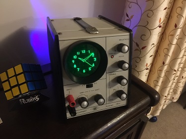
02-inputs/Notes.txt(catahoulatech.com PCB; sgitheach.org.uk/scope2.html software; nycresistor.com vector display tutorial). - Community enclosure and steampunk reference collection,
02-inputs/Picture Ideas/(e.g.CRTclockfront.jpg,CRTclockside.jpg,CRTclockquarter.jpg,CRTclockmountingclips.jpg,WattsScope2.jpg,coppersteam_01.jpg, and theSteampunk-ish/gallery) — enclosure and styling reference for this build. - Small brass steampunk parts and jewelled indicators,
02-inputs/CRT Data Sheets/JL2/— vendor links galenacenturyradio.com (century-radio parts) and amprepairparts.com/jewels.htm (amplifier jewels), for decorative trim. - Steampunk subproject context,
Clocks/Steampunk/CLAUDE.md— the broader aesthetic / materials library this volume’s treatment is a subset of. - Hub-wide safety reference,
Clocks/_shared/safety.md, and Vol 12 (Safety, Calibration, Troubleshooting) — the full HV discipline this volume’s enclosure rules implement.
Comments (0)